Musashikoganei Square Wheel
(subtitle: Peaucellier Linkage Wheel)
Today is 2013/02/01
My name is Fumio Imai (Japan). I found the square wheel invention after about 10 years study.
( At first, I researched the alternative wheel to replace the so noisy travel-bag's caster.
--- I think, thought, thought. Leg style wheel. At last, I found this. )
I introduce my idea to all over the world. ----- Please enjoy it.
cf. Related phrases: Reinventing the wheel
1. Application of Peaucellier Linkage
This is made from the combination of 4 orthogonal Peaucellier Inversors.
To see is to believe.
Below is my answer.
This is mathematics, art ( so beautiful, isn't it ?!), mechanical engineering.
Just as the term indicates, the down-to-earth style invention, it's not desk theory. It's useful in real life perhaps.
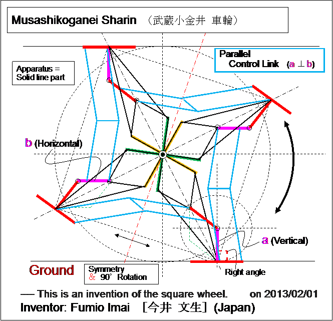
- Fig.1 -
- Parallel Control Link needs in order to restrict the foot stand bottom angle (to choose one from two selections).
( This restriction is an assistant and can improve if more elegant technique exists.
--- just after the inflection point situation ( i.e. After pink and red lines became exactly in line, 2 patterns may exist.). )
- Vertical Pink " | " brings about the constant height, Horizontal Pink "―" brings constant width.
- The Peaucellier Inversor which is touching the ground is the master, other 3 Inversors are the slaves.
- Slide friction mechanism for line-symmetry realization is not needed. --- This is very great.
- Unsurfaced roads are not suitable for this apparatus. --- usual 凸凹 road is OK.
( If the road is bumpy, this wheel brings the smooth-bumpy ride. )
- = Virtual circle wheel which is locally a infinite radius circle
Here is the Anchor name = "cheby_wheel".
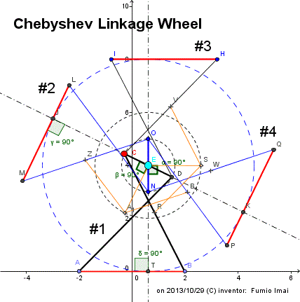
- Fig.1C -
Left figure is a square wheel made by Chebyshev Linkage (approximate straight-line mechanism).
In left figure, the solid-line bars are components of this apparatus. The dashed-lines are explanatory lines.
Aqua-colored big bullet 〇 E is a axis of this wheel.
This apparatus has beautiful property.
① ABCD (= #1) is a basic component.
AB = Lower base (length 4), AD or BC = Cross-oblique sides (length 5), CD = Upper base (length 2).
(We suppose that AD and BC are always crossed. To avoid the uncrossed situation , we must attach the angle limitation stopper. i.e. Keep BP ≧ 0.)
This apparatus has 4 components (#1,#2,#3,#4). #1 and #3 are point-symmetry each other. #2 and #4 are, too.
② #1 and #2 (LMON) position relation has next rule.
a) Lower base ⊥ others Upper base.
From a), ON (#2 Upper base) is always vertical. ∵ AB is fixed and horizontal.
From a), LM (#2 Lower base) is rotate 0 to 180゜. ∵ CD rotates 180゜.
[ In same component, Lower and Upper bases move alternately each other. i.e. When one is rotating, the other is not-rotating. ]
Rule a) is established by various ways, but, the most simple way is used in left figure.
i.e. R = the middle of BC (length 2.5 [= 5/2] ), Suppose S , RS = length 2.5, ES= length 2 [= 4/2].
From theoretical analysis, ES // AB. --- so, To make ON ⊥ AB is equivalent to to make ON ⊥ ES.
(We can reduce the number of bar by this way.)
At the end, Force to fix the angle between ES and ON toward 90゜. --- welding/ glue.
I think this inventions is a home-run hit in the human being history.
(This figure was made by GeoGebra Graphics View's copy-function. GeoGebra is powerful educational tool.)
- Fig.1C -
Here is the Anchor name = "cheby_oval".
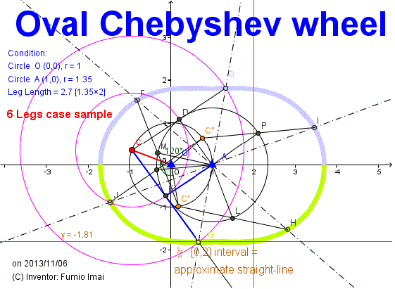
- Fig.1C_oval -
Left figure is my modification of Chebyshev Linkage.
In general Chebyshev Linkage makes a trace reverse 凸 (convex).
straight segment and under arc (Not upper arc.).
under arc is a bad feature, indeed.
Tuning the length of composing bar.
Result is the left.
Peanuts cell/ cocoon/ egg style figure exists.
1 red bold bar (= crank), 2 blue bold bars is basic component unit.
6 legs figure is the left (i.e. at least one foot exists in interval [0,2]). 8 legs case is hopeful (i.e. at least one or two feet exist in interval [0,2]), too.
Keep OA line to be horizontal (by man-power), then the height becomes constant.
In spite of discrete (= not continuous) tire, it's enough.
Point A is on the arc of circle O. This is important.
Ratio 1:1.35 (or 2:2.7) is important. So simple is the best important.
Is there another better numerical value? Please search/ find.
Cassini oval is general this figure? --- may be. very near. Anyone more research/ deepen, please.
In other words, This is the new drawing apparatus for Cassini oval/ lemniscate curve.
This is great invention/ discovery?
cf. Lemniscate of Bernoulli (Arseniy V. Akopyan) --- mathematical proof. related Linkage apparatus.
If try&Err attempt, foci were (1-1.42,0), (1+1.42,0) , then (distance from foci)*multiply = 5.29 to 5.66 --- i.e. not constant, So, this curve is not Cassini curve. perhaps.
but, I call this apparatus "Cassini wheel" for convenience sake.
cf. 3 Legs wheel (I found interesting animation of Chebyshev linkage application.)
cf. The Design and Optimization of a Crank-Based Leg Mechanism (pdf)
cf. Giovanni Domenico Cassini (Wikipedia)
(June 8, 1625 ? September 14, 1712) was an Italian/French mathematician, astronomer, engineer, and astrologer.
cf. Cassini-Huygens (wikipedia)
---- (named after astronomers Giovanni Cassini and Christiaan Huygens) is a flagship-class NASA-ESA-ASI robotic spacecraft sent to the Saturn system.
- Fig.1C_oval
-------------------------------------------
Here is the Anchor name = "Cassini_square".
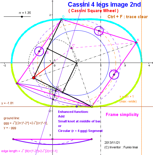
- Fig.1C_Cassini -
I name this invention "Cassini Square Wheel".
This is 4 legs case in above apparatus.
In this case, good property are there.
This is simple enough, useful in real life, easily-assemble wheel, at emergency use, non-bulky/ saving storage space, easy cart, separable storage, only a bar.
From my experiment, radius of Circular Segment for edge is about 4 ggg.
The theoretical curve is almost circular, perhaps.
Please prove this hypothesis.
And I say that No needed rr=1.35, rr ≧ 1.35 is OK, and radius of Circular Segment ≦ 4 ggg.
Please try DEMO, and feel what I said is true.
- Fig.1C_Cassini -
Tip: approximate radius R was estimated from below. (rr = 1.35 case)
hw = half width of egg = 2rr --- hw = 2.7
hh = half height of egg = ggg = sqrt(4(rr)2-4)=2sqrt((rr)2-1) --- hh = 1.813836
he = half length of edge = sqrt(8(rr)2-4)/2=sqrt(2(rr)2-1) --- he = 1.626346
c. egg width : height = 2.7 : 1.8 ≒ 3 : 2
Calculate R: --- cf. Circular segment (wikipedia)
c =2he=2Rsin(θ/2) --- Rsin()=he
h=hh-he=R(1-cos(θ/2)) --- Rcos()=R-(hh-he)
So, (he)2+[R-(hh-he)]2=R2
(he)2+ R2-2R(hh-he) +(hh-he)2=R2
R = [(he)2 + (hh-he)2] / 2(hh-he) ----- 7.147450151 [where, (he) = half of chord, (hh-he) = depth of circular segment]
ratio = R/ggg = R/hh = 3.940516825 ≒ 4 (rr = 1.35 case)
c. Slipping circular curve is the same in Reuleaux triangle case.
c. This is a kind of Continuous track (or caterpillar track).
c. It is easy to create this. Please make this wheel bicycle/ car/ cart, and demonstrate it in public. I welcome it. (by Fumio Imai on 2013/11/24)
2022/05/31 この図は、かなり奥が深い。pink の線分が固定長であることの証明が思い出せなかった。
赤● が B のとき、黒太線はペッたんこ状態。G は x 軸の左端。BG = 2 rr。K は B の真上の一番高い点(高さ ggg)。なので、pink 線分の長さは、√((2rr)^2 +ggg^2)。
また、CC' = 2, C'K = 2 rr。 C'K の中点は B から rr の距離。軌跡は円。 Pink 線分中点は B から 0.5 (Pink 線分) の距離。軌跡は円。--- つまり、てんこ盛り機能。
線分 OBM の平行棒を使用すると、8 本構成システム可能 但し軸 B の負担増。implementaion は case by case. で良く考えて。
-- implementation 時の comment --
この車輪は、2つの円運動の合成となる。軸アリ円にすると衝突が発生してしまう。赤●の軸は、ピンク棒と衝突しない。なので、赤●の円軌道は、軸ナシハンドで回す様にすると良い。--- 言っている意味分かりますか?。少し、高級。
/* ↑ ここの html coding 部(日本語 code)は、project2 では「コード変換して保存(Y)」と、再読み込み必要 */
--- unocode ---
2022/05/31 この図は、かなり奥が深い。pink の線分が固定長であることの証明が思い出せなかった。
赤● が B のとき、黒太線はペッたんこ状態。G は x 軸の左端。BG = 2 rr。K は B の真上の一番高い点(高さ ggg)。なので、pink 線分の長さは、√((2rr)^2 +ggg^2)。
また、CC' = 2, C'K = 2 rr。 C'K の中点は B から rr の距離。軌跡は円。 Pink 線分中点は B から 0.5 (Pink 線分) の距離。軌跡は円。--- つまり、てんこ盛り機能。
線分 OBM の平行棒を使用すると、8 本構成システム可能 但し軸 B の負担増。implementaion は case by case. で良く考えて。
-------------------------------------------
Here is the Anchor name = "cheby_egg".
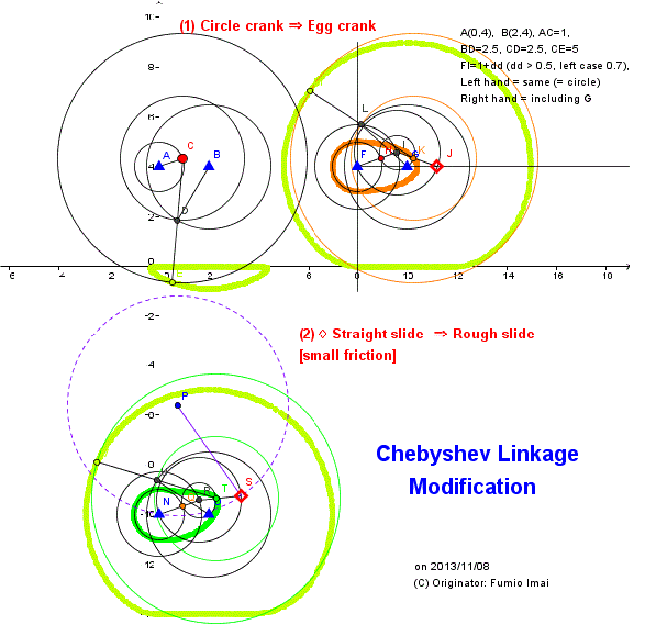
- Fig.1C_egg -
About left orange egg curve apparatus,
I define this apparatus name for convenience sake
(including next Crescent Moon shape apparatus):
Circle-Ellipse hybrid curve linkage
---- [alias: Imai Linkage]
(i.e. Half is circle, another half is ellipse mixed shape)
Please see DEMO for more information.
------------
I'm convinced this simple Crescent Moon shape apparatus is worthy of the name "invention".
Because, this makes a walking leg system from Peaucellier Linkage easily.
I pondered the apparatus of such curve making, but I couldn't for many years. I gave up this matter.
But, "Unexpected things often happen." I found one answer.
Left apparatus is tricky like a magic trick.
(simple, but powerful.)
God is very whimsy. I think So.
c. This trick is similar to Geneva drive trick somewhat.
---------------------------------------------------------------
Here is the Anchor name = "crescent".
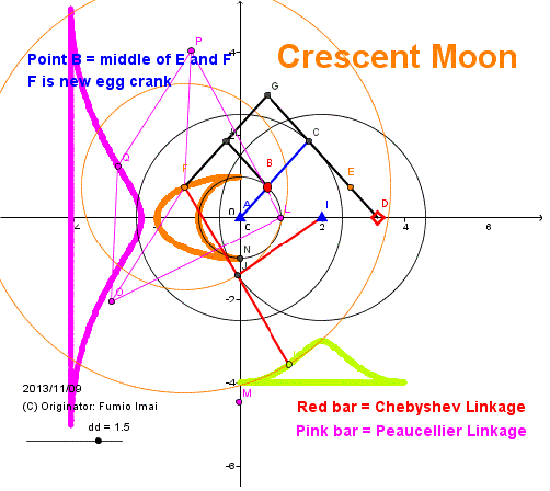
- Fig.1C_crescent -
B rotates on circle A.
Slide ◇ D moves on x-axis (x ≧ 0), and never move -Minus x area.
When B is in -Minus x area, D is stopped/ remained on A, and all black frame are shrunk as 1 bar, so F/B/E locates the same position. That is, F/B/E moves on left half circle.
When B moves into Plus x area, F/B/E changes into un-shrunk different situation, B draws circle, E draws right ellipse, F draws left ellipse.
As a result, F draws Crescent Moon figure.
(Ellipse may not be a true ellipse. (?))
Tip:
This fig. is interesting. Peaucellier Linkage is an INVERSOR (6 bars part), and, Chebyshev converter makes similar trace (but, 90° shifted), if so, Chebyshev converter (2 bars part) has an approximative INVERSOR property.
---- WHY? --- Please research the mechanism. 2 is simpler than 6.
- Fig.1C_crescent -
---------------------------------------------------------------
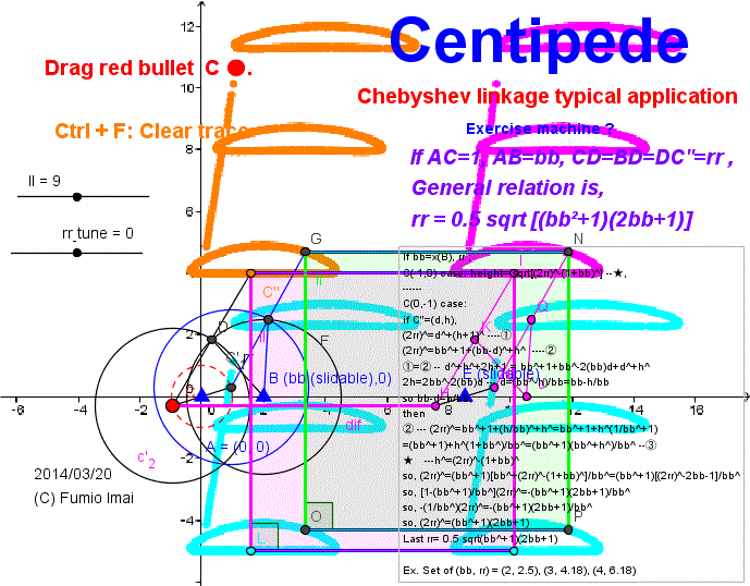
Here is the Anchor name = "Centipede".
, Leg simulation Linkage/ Robot
Hoekens linkage application
Linkage length ratio = 1 : 2 : 2.5 ------ This ratio is basic. (wikipedia)
Generalization = 1 : bb : 0.5 sqrt [ (bb2+1)(2bb+1) ]
Proof:
If bb=x(B), rr ;
red C ●(-1,0) case: height= sqrt[(2rr)2-(1+bb)2] -- ★,
------
C ●(0,-1) case:
if orange C'' ● = (d,h),
(2rr)2=d2+(h+1)2 ---- ①
(2rr)2=bb2+1+(bb-d)2+h2 ---- ② [from ∠CBC'' = 90°]
① = ② -- d2+h2+2h+1 = bb2+1+bb2-2(bb)d+d2+h2,
2h=2bb2-2(bb)d --- d=(bb2-h)/bb=bb-h/bb
so bb-d=h/bb,
then (can eliminate d)
② --- (2rr)2=bb2+1+(h/bb)2+h2=bb2+1+h2(1/bb2+1)
=(bb2+1)+h2(1+bb2)/bb2=(bb2+1)(bb2+h2)/bb2 -- ③
★--- h2=(2rr)2-(1+bb)2 --- (can eliminate h)
so, (2rr)2=(bb2+1)[bb2+(2rr)2-(1+bb)2]/bb2=(bb2+1)[(2rr)2-2bb-1]/bb2
so, [1-(bb2+1)/bb2](2rr)2=-(bb2+1)(2bb+1)/bb2
so, -(1/bb2)(2rr)2=-(bb2+1)(2bb+1)/bb2
so, (2rr)2=(bb2+1)(2bb+1)
Last rr= 0.5 sqrt [(bb2+1)(2bb+1)]
[ Further, h= bb sqrt(2bb) , so, bb-d=h/bb=sqrt(2bb), So, span of straight segment part = 2(bb-d) = 2 sqrt(2bb) i.e. ∝ √(bb) ]
Ex. Set of (bb, rr [span=2√(2bb)]) = (2, 2.5 [2√4=4] ), (3, 4.18 [2√6≒4.9]), (4, 6.18 [2√8≒5.66]) ---- Try DEMO, Please slide the slidable point B ▲.
cf. VTR: Стопоход Чебышева (=Stopohod Chebyshev)
, Walking Table, 体育祭ムカデリレー (=Centipede race in Japanese school athletic festival)
Tip: For the Walking Table or the Cart (i.e. Pushing or pulling man-power cart), I'd like to introduce the slidable parallelogram frame style.
(This is Hart's A-frame application. ---- Large length of stride and smooth non-heavy moving can be realized.
--- i.e. Replace the stilt parts from rectangle to the constant height slidable parallelogram. Please see DEMO.)
----- I think "Chebyshev/ Hoekens linkage needs bigger horizontal moving power than Hart's A-frame mechanizm".
---- i.e. Chebyshev linkage is a bad energy efficiency apparatus perhaps. But, It's needed for the return stroke.
---- Last my feeling: Best this apparatus maybe "Hart's A-frame + circle/ piston slider assistant". Please study more.
c. As a matter of fact, Hoekens linkage is "half-left circle corresponds to horizontal line". --- this is odd (= not honest). power does not transfer directly. 45° angle has shifted. Power loss is occurring. --- i.e. It's dishonest/ bad method.
- Centipede.gif -
- Centipede.gif -
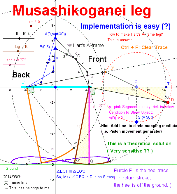
Here is the Anchor name = "Centipede_A-frame". ---- Alias: Musashikoganei leg
This is a general walking leg mechanism/ walking linkage. This is a Legged robot.
Theoretical mechanism of the mapping from Piston movement to Leg trace.
Piston movement : --- ex. Peaucellier linkage/ Hart Inversor/ Hart's A-frame/ Chebyshev-Hoekens linkage (line drawing iteration part only) --- and, real piston slider is OK, too.
( Large r, long long 1 bar [= line curve approximation] is OK, too.)
(New) Leg stroke mechanism model/ walking model:
Feature: Exact horizontal straight line ― + Rigid right-angle sector ⊿ + Crank circle ◯ ⇒ Leg stroke
This is sensitive solution. ground must be flat.
cf. Passive Walking Robot Propelled By It's Own Weight ( Nagoya Institute of Technology, October 25, 2011 )
Below Fig. shape is resemble to the above Robot shape. (??)
---- What relation are there?
(but, below apparatus is backward walking is OK. this is different from above walking Robot.)
Below Fig. has big potential. I think so.
( We can say "This structure is more primitive style than Chebyshev/ Hoekens Linkage.". (???) )
This is considerable good & smart. Energy-saving type (?).
(This is a kind of Hysteresis curve generator. --- i.e. go and back routes are different. )
cf. 知らなかった・・・・: 佐藤ロボット研究所不定期日誌 --- Please click 2nd Figure. Animation will start.
(Heken Linkage --- Hoekens Linkage?)
cf. 脚機構・・・: , 歩行機構について2: Please click Figure. Animation will start.
Tip: Hart's A-frame can exchange the top/ bottom layout. Because, distance from point A to point E is constant, this is equivalent to, from E to A is constant.
c. Watching below figure, It looks like easy work to make a walking bicycle.
ex. front wheel remains usual bicycle wheel, and rear wheel and pedal parts are replaced to below part. Circle C is pedal itself. Length ll bars are chain itself. --- perhaps, OK.
Tip: Please make no crank system (or, otherwise/ alternative, always constant radius rr, is allowed.) and get the same result.
i.e. delta is constant (or constant foot arc size). independent from bar length (value
leg bar in the Fig.). Leg angle is dependent on only stroke position proportion in stride. ex. delta = 10°
In outward leg angle: @left end = 90° (
= just vertical), @about middle = 90° + delta, @right end = 90°
In return leg angle: @left end = 90°, @about middle = 90° - delta, @right end = 90°
Please make such apparatus. --- This is a normalization/ canonicalization problem.
• One answer is, Insert the amplifier to the (unit-piston + unit-crank) existing part, and get the new wide piston.
--- but, needs adding bars. it's not good.
Example: To manage the A-frame by the unit-crank directly.
ex. Managing the point N's or K's (in below Fig.) horizontal position by unit-crank. A-frame doubles as the amplifier role. And add the parallel linkage mechanism (i.e. increse 4 bars).
Bicycle can be applied this. ∵ bicycle is the crank driven system.
---- See/ Try Java DEMO (10_d). ☟
- Centipede_A-frame.gif -
∠DEO' = 90°, ∠D'E'P'= 90° are the key.
Point Q is contact position to ground.
Arc O'O'', P'P'' are partial tire.
Make a centipede by multiple legs connection in series (i.e. tandem).
Question:
Point Q movement distance from right to left (= stride) is circle C diameter.
But Arc O'O'' length (= foot size) is less than circle C diameter.
----- WHY?
(Answer: circle E radius EO' is not real wheel. This apparatus is a virtual wheel system. Virtual radius is bigger than real radius.
Foot size of this apparatus is less than a half of circle C diameter.)
- Centipede_A-frame.gif -
Here is the Anchor name = "Centipede_Bicycle". ---- Alias: Musashikoganei Bicycle
Walking Bicycle
c. This structure is somewhat resemble to Next apparatus. ----- in akin group.
• Walk mechanism. LinkageSimulator 歩行できそうなリンク機構1 (YouTube: Japan) (by (C) hamakouH, 2009/10/28)
cf. 1928 – Meccano Walking Tractor – A. L. Spilhaus (Sth African) and C. Lee (British) --- See real picture.
( ---- It is anticipated that the tractor will be particularly useful for agricultural work, for it may be used for hauling ploughs and harrows over rough land, and used also for other farm duties.)
cf. 2012 – “Octipes Vehiculum” Human Powered Walking Machine – Silas Ulbrich (German)
|--- 1981 – “Joggercycle” Hybrid Walking Bicycle – (Japanese)
|---- Posts Tagged ‘Human Powered Vehicle’
cf. The Design and Optimization of a Crank-Based Leg Mechanism (.pdf) (©Amanda Ghassaei, 2011 )
|---- Chapter 3: Survey of Walking Mechanisms and Analysis in
Mathematical
|---- §3.2 Hrones-Nelson Mechanism
(--- Theo Jansen mechanism simplifies to a model that is identical to a Hrones-Nelson mechanism ---)
( §3.1, Fig.3.1.2 quotation: --- The Hrones-Nelson and Theo Jansen mechanisms are shown below demonstrate
the similarity of their designs. The Hrones-Nelson mechanism is comprised of one
triangular structure attached to a four bar linkage whose movement is driven directly by a
crank. The Theo Jansen mechanism is comprised of two four bar linkages attached to
each other in series with only one of the four bar linkages driven directly by the crank;
the four bar linkages share one hinge in common and are separated by a rigid triangular
structure on one side. Additionally, another rigid triangle is attached to the linkage to
create the “foot” of the mechanism, as is the case in the Hrones-Nelson model. --- )
c. Musashikoganei leg mechanism also is resemble to a Hrones-Nelson Mechanism. I think so.
c. I can't pronounce Hrones. UK original?
cf. Land Locomotion Laboratory
Research Division
Research and Engineering Directorate
THE MECHANICS OF WALKING VEHICLES (.pdf) by ©Joseph E. ShigleyJoseph (September 1960)
( ---- same material read only, The University of Michigan. Can't retrieve etc. -- bad!!)
cf. walking bicycle (YouTube) --- somewhat clumsy (???) --- and too slow!!!.
cf. Assignment Discovery: Walking Mechanism (© 1998-2014 HowStuffWorks, Inc)
cf. The Humble Velocipede ---- Theo Jansen bamboo TOY
-----------------------------
c. related material.
• Klann linkage (wikipedia)
|--- How does Klann's Mechanical Spider Mechanism Work? (animation) : 2 bars + 2 bent bars + 1 crank bar [sum 5]
• JANSEN - KLANN LINKAGE COMPARISON
|--- How does Theo Jansen Mechanism Work? (animation) : 4 bars + 2 bent bars + 1 crank bar [sum 7]
Tip:
• Musashikganei leg:
|---- (Hart's A-frame type) : 5 bars (= Hart's A-frame) + 1 bent bar + 1 crank bar [sum 7]
|---- (Hoekens Linkage type) : 3 bars (= Hoekens Linkage) + 1 bent bar + 1 crank bar [sum 5]
| ----- Hoekens is not fit for Musashikoganei leg. ∵ it's too weak structure.
|---- (Chebyshev Linkage type) : 3 bars (= Chebyshev) + 1 bent bar + 1 crank bar [sum 5]
|---- (Long radius circle type ) : 1 bars (≒ ∞ radius arc) + 1 bent bar + 1 crank bar [sum 3]
Q: I can set the point B to the middle of JJ'. How to? (my secret. ,,, add + 2 bars ?) ---- but, There's no merit.
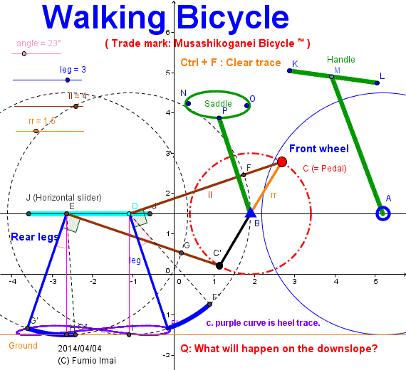
- Centipede_bicycle.gif -
Maybe Tired exercise ???
Q: on the downslope?
A: perhaps, passive automatic walking endlessly.
(--- It's evident (?).)
If tri(= 3)-legs were supported, more smooth downward action will be realized. but it becomes complex structure (so, I don't recommend).
[i.e. Please make 120°-120°-120° triangle crank pedal. ]
This is a
Musashikoganei Leg
application.
I'd like to put on shoes to this feet like below site.
cf. The Walking Bike (Copyright © 2014 Newlaunches.com)
|--- superted walking bike (YouTube) --- looks so tired to run.
- Centipede_bicycle.gif
Here is the Anchor name = "Centipede_Cheby_leg".
Leg by Chebyshev Linkage
I introduce the Chebyshev linkage sample applied to the Musashikoganei Leg.
Chebyshev linkage is (5, 5, 2) length three bars symmetry apparatus [ where, long bars are crossing ]. it generates the approximate straight-line.
Its trace is equivalent to Hoekens Linkage.
[ height 4, width 4, and, (3, 4, 5) right triangle is composed. ]
Chebyshev's structure is stronger than Hoekens' structure. So, it can endure the heavy weight.
---- Hoekens Linkage is too slightly-built. --- i.e. weak.
c. In order to get smooth motion, I recommend not to use 100% of horizontal part span. Please use about middle 80% area, I think so. Both ends area is tight and has much friction for the moving, perhaps.
ex. In below Fig. orange bar FI (center E) can be taken from -90° to +90° angle,
but in real implementation, should be -70° to +70° angle. 20° (= 90°-70°) margin should be remained.
--- i.e. moderate diet/ eating or abstemious.
--- Please do the try and error. (or +-100° is possible? --- I don't know.)
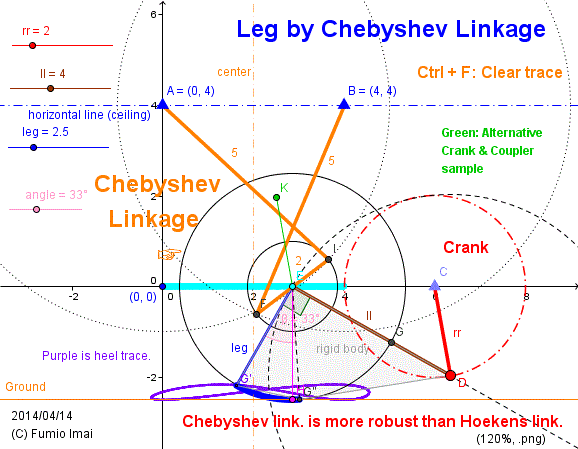
- Centipede_Cheby_leg.gif -
(This is a
Musashikoganei Leg application.)
If set the value leg short,
the point E looks like an ANKLE?
Heaviness tolerant structure.
Good Robustness. (?)
Resemble to
(SL) Locomotion mechanism.
cf. George Stephenson and the railways -- See picture.
( There exist analogy. )
The word "locomotion" --- it sounds good/ good sounds.
cf. Terrestrial locomotion (wikipedia)
- Centipede_Cheby_leg.gif -
----------------------------------------------------------------
----------------------------------------------------------------
Leg by A-frame crank
Please compare above Fig. with below Fig.
Exact straight line. Total number of bars is the same as above Fig.
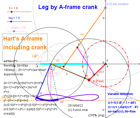
- Centipede_A-frame_crank.gif -
- Centipede_A-frame_crank.gif -
Here is the Anchor name = "Centipede_A-frame_ultimate".
Ultimate Hart's A-frame Leg
Below is last one of answer of Hart's A-frame Leg. Including amplified crank in A-frame itself.
( As of 2014/05/17, the Best answer of Hart's A-frame family's leg is "Imai's Hart's A-frame Leg" -- 5 bars/ leg. )
When Crank pedal C ● is on O' ▼ (θ=0°), D is on the O (0,0) ▲ starting point.
And Pedal C is on End' ▼ (θ=226.57°), D is on the End ▲ end/ turning point.
End is not corresponding to 180° in general (∵ this is amplified case.).
As a leg angle we must manage, at O; Leg angle 90°, at End; 90°.
In order to get this, we provide/ propose the O'-End' - · - · - line slider. If so, the Q of bar CQ (length ll) slides on the such line, when C is on the O' and End', ∠CQO' is 0°.
But angle∠CQO' has imbalanced value, i.e. In right hand of area it is big, and in left hand it is small value. --- we must modify/ adjust/ correct this bias.
i.e. In right hand, to decrease, in left hand, to increase, such mechanism must be produced. --- There exist one solution easily, introduce to the curved slider.
Introducing the circle slider, we lose the just 0° property at O' point (we can get very small value, but can't get zero). but in real world, it's almost enough.
"To see is to believe" ---- Try next DEMO , please.
(Tuning of circle slider is interesting work (?), please try.)
c. ▱ CDQS is parallelogram. --- Theo Jansen mechanism also has a parallelogram and triangle rigid body, is it so resemble to?
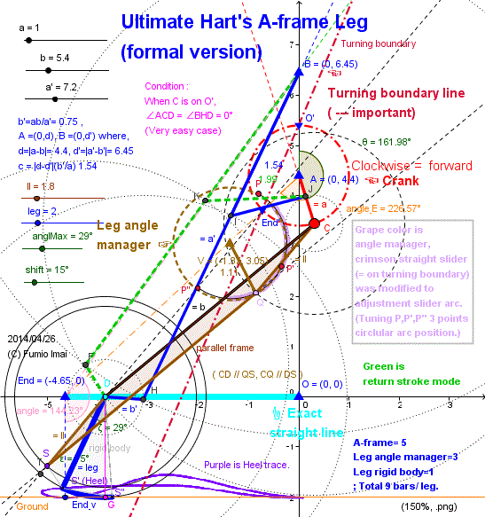
- Centipede_A-frame_ultimate.gif -
Result Circle sliders radius is 1.11 (Crank radius is "a = 1.0").
i.e. Almost the same crank circle. This is a strategy on purpose.
- Centipede_A-frame_ultimate.gif -
Here is the Anchor name = "Centipede_A-frame_exact".
Exact straight stroke Hart's A-frame Leg
Description of latest version of this apparatus is in the next section "Imai's Hart's A-frame Leg".
----------------
(Now, Below description is old version material, but as a history, is useful. )
Below is last answer of Hart's A-frame Leg which has the exact straight bottom shape.
This apparatus is almost the same usual generalized Hart's A-frame, only one different is having the angle restrict stopper.
i.e. In forward process: as the same, no different at all.
At the turning critical point End (4.447,0)/ End', a'-b' angle is just 180°, after this time, the frame change from black & blue to black & green frame.
And If nothing add to this, the new end-point D' runs on X-axis.
And after a bit, short bar b' crosses over the long b bar. at this point, I force to stop/ prohibit the overtaking action by stopper, --- What will happen? ---- the b' is been pulling up by b , but I stop going down, so b' move to upper direction, then D' takes off the ground.
(usual/ old way A-frame, b' is beyond the b, goes up/ left, and D' goes opposite direction , i.e. down/ right)
( i.e. Between the Point G (on bar b) and Point H (on bar b'), set the mark  by Point H. --- very easy.)
At last, Frame becomes pink & green.
(Remark: Here, Point D' runs back on the X-axis until b' crosses over b, so, in order to avoid this, the length bridge c is very small,... etc., is needed. ---- this Back action is characteristic phenomena of this apparatus. (?) --- i.e. a little back and then hovers [= takes off the ground]. --- I don't know this logic, yet. --- difficult.)
As a result, D' draws the Violet color curve.
Please check this logic by yourself using below DEMO.
c. Is this deserving to the invention? ----- perhaps so.
c. This is a kind of a mutation.
c. below curve is resemble to Theo Jansen's curve. Below is a theoretical answer (in meaningly exact straight.) ---- Real animal walking trace curve is near this curve?
c. This result says, angle stopper device is needed. this is near the real world. i.e. Our arm or knee angle can't become more than 180°.
(b-b' between angle restriction: 0° to 180°)
c. This apparatus is considerable interesting. This is a systematic thinking result.
c. Changing of the route often happens in frame linkage when multiple bars overlapped, this is a Ghost route transit phenomena.
ex. + to 0 to - (this is normal), this sometimes change as + to 0 to + (U-turn happens) [point 0 is the point of inflection/ or critical point] , comes from the timing problem.
I abused (or managed) this phenomena on purpose, in order to make the hysteresis curve.
c. I tried to change the route to Ghost route, in the past time. but, failed. But, now I succeeded easily. Perhaps this is related to the a bar can rotates 360° all.
c. Pink curve trace below is ghost, too. but we don't enter that route. Such management is done automatically, perhaps.
c. Please try to do implementation by Hart's Inversor or Peaucellier Linkage.
Perhaps, Much bars are needed (???).
c. Klann linkage, Jansen linkage is resemble to this, somewhat. ---- why? -----, Naturally, because this is the primitive base of such derivatives, I think so.
c. If d < d', trace curve becomes discrete/ discontinuous, so can't exist.
c. Orange lower leg part can replace to the vertical pole (no foot type).
ex. set the 2 Legs in a row/ serially, and attach/ insert/ connect the rectangle to the between and under of each point D.
c. angle γ (/gamma/) is the angle of the case which the C is just on the (0,3) [= the lowest point of the circle C]. i.e. γ = arccos((d-a)/b)
c. d=d' case: a=b', b=a', c=0, this is multi freedom case, so, the position isn't fixed.
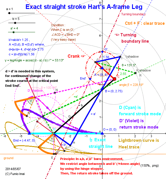
- Centipede_A-frame_exact.gif -
parts: 5 bars/ leg (including arc foot).
Under no restriction:
Go route = Return route
→――――――
――――――←
Under a restriction:
Go route ≠ Return route.
→――――――
↓ (another route)
――――――←
There exists a Ghost route at critcal point.
―――■→―――
↓ (= Ghost branch)
|
-----------------------
This figure indicates "c" bridge bar position on "a" bar,
"b (b'/a') > a" relation happens.
i.e. c is in the back/ after area of the pivot point.
cf. Fig.13 lower picture.
- Centipede_A-frame_exact.gif -
Here is the Anchor name = "Centipede_A-frame_stroke".
Imai's Hart's A-frame Leg
Subtitle: Hart's A-frame having 360° crank is itself a walking Leg apparatus.
( --- I declare that This is one of the great discovery in 21th century.)
I learned that generalized Hart's A-frame natural movement of before Fig. is not the piston iteration, but the walking stroke movement pattern, so, we don't have to intend the overtaking mechanism, because the default movement is the non-overtaking movement mode.
And I learn, d < d' [= crank A circle is under the A' circle ] pattern is better than d > d' pattern.
( My comment as "c. If d < d', trace curve becomes discrete/ discontinuous, so can't exist." was wrong. thinking miss. ∵ There existed b ghost normal route [ upper forward direction] just after b'/b overlapped. )
So, Basically, To make the leg stroke from the Hart's A-frame Linkage, we don't need the additional mechanism. just only the orthodox A-frame itself is sufficient/ enough.
Theorem:
In generalized Hart's A-frame, if the initial angle condition satisfies the next,
condition = straight drawing node angle (∠CGD) on the origin point O(0, 0) = 0°
the node trace does not warp (i.e. at the middle of the process, trace disappear).
and draws the continuous closed loop.
(in ≠ 0° case 100% the warp phenomena happens. discrete/ discontinuous curve. --- 0° is the special angle.)
|
Please prove this.
c. To warp is to break the connection of linking. i.e. being beyond the limit.
c. ∠CGD = 0° is occurs when ∠A'AC = 0° or ∠A'AC = 90° case,
∠A'AC = 0° case is good result. ∠A'AC = 90° case is forward and return stroke both have straight line, so unwanted shape curve.
Tip (know how):
Hart's A-frame Linkage has reentrant loop structure, so, if you were not familiar to the GeoGebra operation, you can't draw this linkage.
This A-frame's each node has independent/dependent relation with other node each other.
So, if mistake has done, the drawing construction will be failed or falls in endless loop thinking. There exist a sequential node making order, Please define/ make the nodes by next order.
Should make/ define/ determine a independent node first. dependent is next/ after.
i.e.
A, A', C, Cpos [on AC, from A distance = a-b(b'/a')], C'pos [from A' distance = a'-b'(b/a), from Cpos distance = c], D [ extend A'C'pos, A'D = a'], at last G [from C distance = b, from D distance = b'].
c. Real natural phenomena has a simple and beautiful mathematical structure in general, if your concept is too complex, it's not good system, against the God perhaps. Because God/ truth is in simple/ nature.
So, this apparatus is simple, ---- perhaps it's near the nature (?).
c. Ghost route problem comes from the double roots of the quadratic equation, 2 circles are tangent at one point, and after, two roots are separate, in this time the we looking point will be switched or not, ------ this is a timing problem. it's related/ influenced by law of inertia, power, velocity, acceleration, disturbance, friction, etc.
So, GeoGebra sometimes tells a lie. In this case is so?, ---- I don't know.
Ex. Below figure is not symmetry, ------ this is odd. (Don't you think so?) ---- this is a telling a lie case?
----- Eventually, we must test the real created apparatus.
cf. Leg style carrier (VTR) (© Nagoya Institute of Technology in Japan) ,,, or NITech Carrying Robot (YouTube, 2011)
∊(included in) parent page: 2009 study (Sano Lab.), ∊(included in) Sano Lab. biped division (©Nagoya Institute of Technology) --- so irritated movie environment, bad/ foolish site, don't touch MPG/ Movie file [∵ much time consume. bad, Windows Media Player trouble happened IE/ Chrome both, server problem? sometimes OK, why?--- conclusion: NITech server is poor.].
----- same thing possible. Below apparatus can use for VTR work easily., Don't you think so? --- Please check DEMO by yourself.
c. Which is Before? Left or Right?
If make VTR carrier, this is the pushing type, so Left is before. Perhaps. i.e. from right to left direction, push/ proceed.
------- In this case, This is the hand pushing/ pulling driven apparatus. by Other leg driven system. Not the motor driven apparatus.
c. BlueBiped (© 2010 Robots and Androids ) says, "Last year, BlueBiped set a Guinness world record after it walked nonstop for a distance of 15 km (9.32 miles), the longest distance that has ever been walked by a bipedal robot. The epic walk took a total of 13 continuous hours to complete, with BlueBiped completing 100,000 consecutive steps without human intervention. It was a singular achievement."
--- I think , why stopped? [13H ,,, is too short !!!.]--- why? not endless, one week possible easily if good apparatus. if this test has done by a complete wheel, it is easy thing to run a week or more. So, for a wheel, easy thing, then the same, for a leg, easy thing.
I think, To make an endless walking leg which walks forever, is easy.
Below leg apparatus would be qualified to be such machine.
------ To help the imagination, below apparatus walks with crank center A's height is constant, and point C rotates 360°. Further imagine, if radius AC is much longer case, if length AC = distance between center A and Ground. This is the large wheel touching on the ground. if such wheel is set on the slope, wheel rotates to the down direction forever. this is natural not unordinary matter at all. So, the same analogy can be applied to below apparatus. Below apparatus is almost nearly equal to the such wheel.
Someone, please do the endless test by below leg machine. left side direction is down slope.
If the wheel run time is endless, if so, below machine is endless, too. ---- it's evident, isn't it?
(Gravity G [= corresponding to the from right to left pushing power], and the low center of gravity not to tumble [= heavy body & G center is in low position]. are needed.)
(If right & left leg one pair and another one pair [sum 2 pairs] are placed in row [ before & after] like a 4 legs animal, it works well.
only one pair leg stand alone case, if right & left foot both touches the ground, slope angle increase, what will happen? ---- before foot becomes supporting point, and push the after foot relatively, i.e. after foot moves to more after and move to the end and hovers and enters the return stroke mode, and move toward the before direction, and catch up the before foot, and overtakes, goes to the top, and touches the ground,,, one cycle has over. ---- repeats this cycle forever/ perpetually.
---- image training is OK.
Perhaps, left-down slope and right-down slope, both type is OK.
The ball (rigid body) on the slope will rotates forever. the center of body keeps constant height from the ground. same analogy is fit to the Hart's A-frame case. The point A or A' node vertical position from the ground keeps constant. A-frame is not rigid body (i.e. has a moving parts/ components), but its condition satisfies the specification for rotating. (?)
Worst-case supporting scenario: In order to ensure not to tumble, absolute method for this apparatus, furthermore, add to 4 paralell bars for each leg (i.e. sum 8 bars adding), to ensure A'A is always vertical to the ground (i.e. bars // to A'A , and ⊥ style foot, adding). ---- [4 legs animal leg style case is ensured this vertical property by another method.]
Increasing the number of bars, but non-stop walking is ensured. ---- At any rate/ Anyway, the non-stop bipedal walking by stand alone leg is not the difficult matter.
---- See, below "Imai's Hart's A-frame 7.5 Leg for Non-stop record" or more its derivatives [5.5 Leg].)
Improvement for GUINNESS Book: Below 5.0 simple type can be endured for non-stop trial, by wearing the very long toe shoes Crakow (shoe).
i.e. Attach the long flat plane tangent to the top of Toe not to tumble.
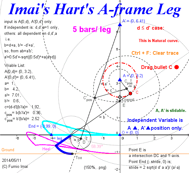
- Centipede_A-frame_stroke_1.gif -
Left apparatus has no angle check controller.
No angle dependent parts.
but, acts correctly.
I did nothing except procedure to usual A-frame. Left is usual/ ordinary A-frame itself.
- Centipede_A-frame_stroke_1.gif -
Tuning is automatically defined, we only have to set the d, d' 2 values.
-----------------------------
The stroke stride length is given from next formula.
stride = 2 sqrt(d d' a a') / (a'-a)
Proof ( Here, I abbreviate 2 notation, and use ^: ex. a^ is meaning as a2) :
This is bar b and b' overlappint point.
See, below environment Fig.
∠GDA' = GCA (This is A-frame general property) --- so, b (GC), b' (GD) are overlapped case, A'D // AC, -- So, △HDC ∽ △ACE, CH = AA', CA=HA'
CE=a(b-b')/(a'-a)
ED=(b-b')+CE=(b-b')(1+a/(a'-a))=(b-b')a'/(a'-a)
GE=b+CE=b + a(b-b')/(a'-a)=b(a'-a)/(a'-a)+ a(b-b')/(a'-a)={b(a'-a)+a(b-b')}/(a'-a)
=(ba'-ab')/(a'-a)
Further,
AE=a (d'-d)/(a'-a)
Then, EO=OA - AE= d-a (d'-d)/(a'-a)= {d(a'-a)-a(d'-d)}/(a'-a)=(da' -ad')/(a'-a)
Therefore, OG=sqrt(GE^-EO^)=sqrt((ba'-ab')^-(da' -ad')^)/(b-a)(a'-b')aa'
numerator part = (ba'-ab')^-(da' -ad')^
=(ba'-ab')^- {(b-a)a'+a(b'-a')}^
=(ba'-ab')^- (ba'+ab'-2aa')^
=(ba'-ab'+ba'+ab'-2aa')(ba'-ab' -ba'-ab'+2aa')
=(2ba'-2aa')(-2ab'+2aa')=4(b-a)a'(-b'+a')a=4(b-a)(a'-b')aa'
then OG=2 sqrt((b-a)(a'-b')aa')/(a'-a)
then
OG = 2 sqrt(d d' a a') / (a'-a)
from this, we can any stride size from a=1 unit crank.
(It indicates, stride width is proportional to the √ of 4 products d*d'*a*a', and is inversely proportional to the gap/ difference of a and a' (i.e. |a'-a|).)
---- but, from the DEMO experience, totally, this value depends on A position. A' position is smaller effect. why? but, this is true. --- interesting.
( related: 1/(a'-a) = (a+a')/(ad+a'd') symmetry form. )
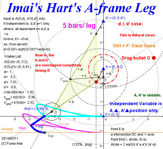
- Centipede_A-frame_stroke_1_stride.gif -
Left is stride size calculation formula picture.
58.39° angle value indicates the Heel-Toe maximum angle. This angle comes from the point C is just on the point Lower. ---- this is given, = arccos ((d-a)/b) function value.
- Centipede_A-frame_stroke_1_stride.gif -
Here is the Anchor name = "Centipede_A-frame_vertical".
Imai's Hart's A-frame 7.5 Leg for Non-stop record (Vertical Leg)
Please someone, Challenge the Guinness Book of Records by this family, in bipedal non-stop walking class.
---- One year non-stop is easily possible, perhaps. (?)
This is the technique to keep/ ensure AA' line is vertical.
In order to realize this, I make AA' the vertical leg parts. i.e. Exchange (turn upside down) the head to the bottom. ∵ height is always the same. --- i.e. head ⇔ foot, exchange just only.
(if not use exchange head/ bottom method, +8 bars increase happens. i.e. sum 18 bars/ 2 legs system)
By this wisdom, We can avoid the tumbling/ upset.
To keep one pair leg walking perpetually on the slope, this technique might be needed for stable motion.
If one leg touches the ground , so stands vertically firmly, so the upper part of this system will incline by Gravity G (= self weight), then Point P ▲ is pushing/ pulling (← or →) by constant power, so this power moves the other leg, action is very restricted, so other leg move pattern is only one, ------ then, this system walks (or remains stopping ---- if so, more tuning is needed. ).
heavy node P ※, light foot/ frame, long upper half (HC' or UC part, point H/ U is pivot point of the leverage/ lever) leg may be effective?. but below structure is robust/ tough, so tuning is hardly needed, I think so. What is needed is acute slope.
※: More precise expression: to get/ amplify the gravity G power influence, Extend/ enlarge the HC' bar, add C'C'' dummy weight part (i.e. HC' → HC'C''), add long tail (if necessary, add the lead weight), a balancing toy effect is expected, flexible bar is good?, small inclining amplifies to big incline (small bow/ bowing angle amplifies to large bow angle), sensibility up effect, is related the law of inertia (this is key point), related Counterweight effect, Flywheel, ...
Last necessary condition: ------ now, after Deep thinking, the energy/ trigger is gravity only, so, heavy node P and very light (= not heavy) all other parts, that's all, perhaps so. other tuning is no needed. --- result is very simple.
(The power which induces the Bowing a head (= point
P) deeply. Such power is needed. Power which can lift one leg completely. and Needs that at angle 0° the motion does not stop. ---- so, acute slope angle is needed.
in order to break the stopping, suppose crank bar including a rolling ball. what will happen? cf.
The Tumbling Toy. ,
Japanese Toy "Mayudama korokoro",
Paul Scheerbart's Wheel. Movimiento Perpetuo,
Movimiento Perpetuo,
Schriber Power Wheel (somethig near?),
GRAVITY Wheel demonstration # 3,
Gravity Arm
---- I think, no needs such additional ball, from seeing Paul Scheerbart's Wheel, A-frame 5.5 is itself becomes perpetual motion machine, too. [moving other leg parts has corresponding to the ball effect.])
Tip: slope angle must be changed during the non-stop walking. if the angle doesn't change velocity becomes numerous/ infinity. so, must be low slope mix.
i.e. The speed down controlled slope is needed.
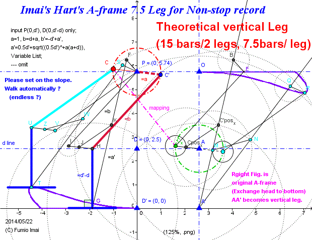
- Centipede_A-frame_stroke_75.gif -
Right hand fig. was inserted by me to display the corresponding relation to the ordinary Hart's A-frame motion.
To tell my confession, it's difficult to draw left hand apparatus by GeoGebra without the right hand information.
At least, in my case. I couldn't (i.e. I failed). --- This figure is beyond my ability. I'm poor.
Tip: right had case: 9 beas/ 2 legs system (crank bar shared, -1)
------------------
Left is equivalent to right;
in right: Mr. A' said "I'm center in the world."
in left: Mr. E said "No kidding!. I'm center in the world."
both are true, comes from different view point.
Key point: I wanted to keep crank HI's 180° opposite side is UV. i.e. HI // UV. the aim of adding parallelogram is to realize it.
- Centipede_A-frame_stroke_75.gif -
Imai's Hart's A-frame 5.5 Leg for Non-stop record (Vertical Leg)
subtitle1: Imai's Invertible Hart's A-frame Leg
subtitle2: Simple and the most solicitous theoretical bipedal system
subtitle3: worthy to challenge Guinness Book of Records
7.5 Leg can reduce the number of bars by the complementary/ conjugation equivalent conversion.
[,here, 2 bar a, b and between angle α, if so, its complementary is b, a and α. i.e. a, b position order are exchanged. ]
( This discussion needs somewhat deep understanding of Hart's A-frame exact line drawing system. but, don't mind. Use only the result.
--- object(+,+), object(-,+), object(-,-), object(+,-) 4 mirrors exist. between them, there is a interesting rule, and trick.)
i.e. In spite of the vertical leg (having additional property), number of bars is almost the same as ordinary A-frame leg. Hart's A-frame method has good property, therefore, is better than others.
Tip:
• Complementary frame was applied, and then, the bridge bar interface has changed to the external division point from internal division point.
• The 7.5 vertical leg method has few merits at present time (?). but no need additional leg parts.
In general, the increasing of parts/ components loses the simplicity, becomes heavy system.
c. Sometimes 7.5 Leg is better than 5.5 Leg. ex. if want a short stride and long leg case, shorten the distance PD, but in 5.5 Leg system becomes very large bridge bar (∵ external division case is apt to be so.), in 7.5 Leg system not occur such thing. is short bridge bar.
• Non-special condition needed, only a invertible type of usual Hart's A-frame.
• After playing this DEMO, I thought " from left to right direction walking (i.e. clockwise crank rotation) is HONEST & NATURAL.
because, in return stroke, foot moves down from upper-left to lower-right position, this is obeying the gravity law/ rule, it's so natural."
So, for Slope down non-stop test, left-high slope is good (?). Please test/ try/ & check it out.
c. Theo Jansen, ---- his name Theo comes from Theoretical, Theory?
c. Deskbound discussion: standing on T letter styled stand F (firmly stands, vertically), in this situation, if point P were pushing from left to right direction by Gravity power constantly, P moves to right (i.e. inclines), but by restriction exists, P height is constant, so inevitably crank rotates (i.e. C' rotates clockwise direction), then opposite side C moves correspondingly, so C return stroke proceeds, and after a while, Foot I reaches the ground, at this point the role of feet F and I are exchanged, I becomes master, F becomes slave, --- one cycle has over. repeats this cycle forever. ---- i.e. walking continues forever, if any trouble doesn't happen.
c. About the bottom of T letters stands, right base edge length is so long, and left base edge is short. ---- this is OK. --- like a kangaroo leg.
cf. YouTube: Toy; PENGUIN-PINGUINO, How to make a Hopping Kangaroo,
Toy Physics - Part 3: Waddling Duck, ---- Nonlinear Dynamics of Wooden Toys --- very simple !!!.
Magnetism & Gravity Perpetual motion machine --- Great
c. Additional explanation; GHC'PA1G frame and its bridge BC1 is typical A-frame shape, in this point if 2 points G, H are fixed, the degree of freedom of this frame is 1 (i.e. freedom not 0, so, movable. i.e. P can move on horizontal line. and Crank angle fixed, C fixed, freedom becomes 0, then body fixed. ), so one more condition is fixed, this body will be fixed. this is easy thinking matter.
On the other side, see the PCUTD1 frame, this frame is hovering now, why doesn't this shape collapse?, at least 2 points P, C are fixed now, degree of freedom is 0 (i.e. C angle is fixed). right hand frame case HG // UT was ensured (AA' is only one bar.), so HG // UT is ensured,too. (perhaps. --- please prove. from equivalency between left hand and right hand), in return stroke there is not angle critical point, so HG // UT property is kept (perhaps).
----- please prove HG // UT by mathematics. (This is good mathematical problem. level: high school. here, don't use right hand figure.) (i.e. HG is always vertical. )
( UT side degree of freedom is 0, is it true? UT can move un-vertical position?. It looks vertical, is hanging only? hanging or not?, ------ my result, this is not hanging. precise expression is "HG // UT".
4 bars frame PCUTD1 is changeable. 4 bars frame UFE1T is also changeable. but, in real system, bar FU and UC are colinear(on the same line) and E1 and TD1 are the same, so, freedom decreases, total freedom is 0 in general. [ 5 bars frame CFE1D1P and bridge UT , but not triangle , so freedom > 0 ??? , hanging? ,,, which is true? --- from my intuition, this is hanging. hanging or vertical both is well/ good. end!!!.
But, when Opposite 180° leg is supported, parallel to opposite leg, so, parallel to vertical, therefore vertical property is ensured.)
c. Analogy between Chebyshev Linkage (YouTube) and A-frame 5.5 Leg: there exists a very similar property.
(YouTube VTR: frame motion is similar to 5.5 Leg frame motion.)
i.e. in chebyshev quasi straight line drawn by crossed frame [= X style]. the return stroke curve drawn by un-crossed frame [= O style].
----- this is the same property as A-frame 5.5 Leg case.
Please someone, clarify this riddle.
More precise expression, in foward stroke ---- crossed like 3 or4 bars frame shape, in return stroke ---- un-crossed like 3 or 4 bars frame shape.
----- So, 5.5 Leg might be a generalized Chebyshev Linkage.
c. P(0,d') is small (i.e. d' is near zero) case, the trace almost becomes typical KLANN curve. i.e. stride is short and height is high trace shape. but this base line is exact straight line.
cf. MECHANICAL SPIDER/ CONCEPT (© 2009 Klann R & D, LLC All rights reserved) Enable001 to Enable008 / curce of variety.
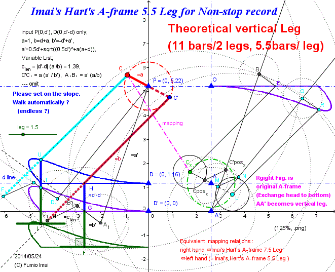
- Centipede_A-frame_stroke_55.gif -
Right hand fig. was inserted by me to display the corresponding relation to the ordinary Hart's A-frame motion.
To tell my confession, it's difficult to draw left hand apparatus by GeoGebra without the right hand information.
At least, in my case. I couldn't ※(i.e. I failed). --- This figure is beyond my ability. I'm poor.
Tip1: in left hand, clen bridge bar changes to the external division points.
So, adding green vertical leg is needed.
(in right hand case; Cposx, C'posx was internal division points. )
Tip2: in this sample case, 2 feet F, I touches the ground at same time, gap distance FI = 4.0 to 3.7 (= almost constant), delta =0.3 ,,, stride = 4.5 , so 0.3/4.5 = 1/15=2/30= 6.66% slipping order. --- within allowable error.
※ Now, I can. without right hand information.
Solution: define x(G) = x(H), y(G) = y(H) -(d'-d) ------ that's all.
(i.e. point G is the unified point with H) ---- again failed. At last, I've succeeded.
See "How to make the vertical leg from Imai's Hart's A-frame Leg" in next section.
- Centipede_A-frame_stroke_55.gif -
------------------------------
y(D) < 0 case variation;
bridge bar interface changes to internal division point, so compact / stronger structure than y(D) > 0 case. (?) and, short adding leg size.
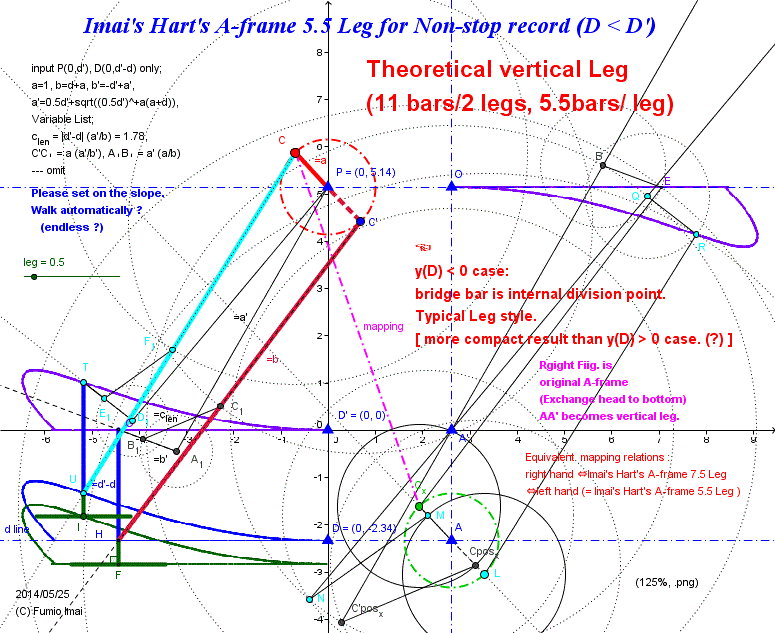
- Centipede_A-frame_stroke_55_vari.gif -
in right hand, original bridge bar interface is external division.
- Centipede_A-frame_stroke_55_vari.gif -
How to make the vertical leg from Imai's Hart's A-frame Leg
I introduce the more direct conversion method to make the vertical leg type Hart's A-frame.
This is Intuitive equivalency.
GeoGebra animation can be made.
i.e. At first, make both blue frame and green frame, and at last, assign the invisible man role to the blue frame.
c. This is also a new 7.5 Leg implementation.
Tip: Imai's Hart's A-frame Leg is a theoretical result, so there is none of ambiguity for frame length tuning value (except d, d' and a).
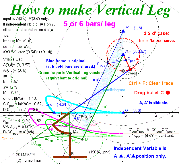
- Centipede_A-frame_stroke_vertical.gif -
2 bridge bars are paralell. --- why?
interesting property.
- Centipede_A-frame_stroke_vertical.gif -
Here is the Anchor name = "Centipede_Inversor".
Imai's Inversor Leg
Consider the Inversor Linkage from the view point of the analogy of above Imai's Hart's A-frame Leg.
Peaucellier or Hart's Inversor has like a crank part. but, near the Pole angle part is corresponding to the -+ ∞ parts, not is corresponding to the return stroke.
But, end of the earth is the back of the earth. If Adjustment has done this motion becomes/ change to the return stroke.
That is, change the direction and change the length.
Result is below. ---- honest, result.
---- I controlled/ managed the shrinking bar. i.e. In forward process, P' is shrunk to P. In return process, P' is seperated from P. I made such trick.
( This is the valve control.)
Adding Only + 4 bars, we can get this. 4 is the same of pantagraph frame bar number.
Chebyshev + pantagraph = 3 + 4 = 7 bars/ leg/ system.
Below, Hart's Inversor (5) case + 4 = 9 bars/ leg/ system.
----- Which is better?
(Addition; At least below is true at this time.
|-- 2 legs pair by Cheby + panta = 7+7-1= 13 /system [ -1 is 180° crank bar sharing]
|-- 2 legs pair by H Inversor = 9+9-3= 15 /system [ -3 is 180° 2 bars, 1 parallel bar sharing] )
c. This is +4 adding bars solution. Please FIND more compact solution, if possible.
c. Circle A is through point P (= north Pole), and Circle D , too.
There is a secret law in 2 similar relation? duality?
c. I think P' is like the mirror of the south Pole (0,-1). south pole is the underworld, the turning point is the warp point.
And, mirror of B (= + 180° point of B) and its Q are in the secret law, if such law we can find, we can reduce the number of bars. I think so. Please more study.
c. The cam and valve with a lock method is possible. number of bar can reduce, perhaps. The control of lock and unlock is needed, so, motion is not smooth and friction happens (?). Please try.
c. This method's turning point crank angle = the start point crank angle + 180°, WHY? ---- i.e. return stroke angle span = just 180°. I couldn't realize < 180°. ---- This is somewhat bad property. --- But, the bottom is completely flat, so 180° span is NO-PROBLEM, it's usual matter. 2 legs pair can keep the horizontal body height. The height down doesn't occur.
To avoid this, please apply another method (ex. cam method).
c. +2 bars method is the one of the best logical result. far superior to +4, +3 method.
Trace curve/ shape is resemble to Klann or Jansen (why?), but it is much sophisticated curve than those (?). --- I think so.
(Klann, Jansen , they didn't know the Peaucellier or Hart name?)
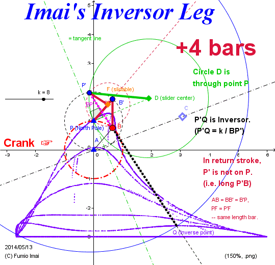
- Centipede_Inversor.gif -
Please tell me.
Unsymmetry, --- WHY?
---------------
Change the height.
Change the width.
--- both is easy.
+ 3 bars implementation
is possible, alternatively.
( but friction increases.)
if you allow, please try.
[Shift point F◆ onto AB bar]
---- Play DEMO (There is +3 sample).
+ 2 bars (non-friction)
exists.
--- This is logical end.
Answer is in DEMO.
[i.e. Hart's Inversor case; total 7 bars/ leg ]
I dare to hide the here answer for student educational consideration, so, you should solve this problem by yourself, and then, please compare your answer to my answer.
- Centipede_Inversor.gif -
Imai's Inversor +2 Leg
+2 bars My answer.
1st My impression: --- +2 method's trace curve is somewhat extreme [ex. height is too high], so I prefer to +4 method, curve management is easier.
(From my experience, +3 method is excellent. It makes a symmetric-like trace curve.)
----- How to avoid this? --- (1) set long A'D radius, if possibile. (i.e. D is far.) (2) set H_angle ≧ 90°(i.e. D is under the x-axis. )
I recommend this +2 method, always H_angle shuold be = 90°. --- this is the most safety value.
No-restriction case is a spider walking machine like as KLANN spider machine.
Otherwise, I recommend to apply +3 method.
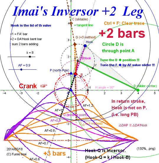
- Centipede_Inversor+2.gif -
Left sample is H_angle = 90° case, so,
B(1, 0) most right --- +4 stride,
B(-1, 0) most left --- -4 stride.
mapping has done.
(k=8, so, multiply ratio is 8/2=4, where 2 = diameter of crank)
cf. AF=1.2 curve is near the Jansen's curve? SOLVE SPACE
(I think, this is not a human walking curve at all.)
[Theo Jansen's linkage = 7 bars/ leg (= same number: Hart's Inversor +2= 5+2=7) ]
------------------------------
Summarize:
Exact straight line drawing Inversor
=
Walking leg linkage
(by adding My magic +2 bars)
[ To warp to the outer space from the earth is equivalent to a return stroke, topologically. ]
-------------------------
[Further surprising result:]
Hart's A-frame exact straight line apparatus (but, crank-type) is a walking leg apparatus with NO(= zero)-adding bars.
~ In a nutshell, Straight line drawing technique is the same as the walking leg technique. ~
- Centipede_Inversor+2.gif -
Imai's Inversor out-crank Leg/ Decussation Bipedal
This is Variation. External unit crank type.
Previous 2 methods "Imai's Inversor Leg" or "Imai's Inversor +2 Leg" are, having the inversor angle moving span is just 90°. This is/ maybe un-natural (?), in general this angle span is more acute and more long leg. stride angle span is more narrow.
(but, average stride angle span is 90° ---- this is natural. case by case.)
Inversor angle span is narrow case: PQ line angle span range is narrow case (i.e. not span 90°, PQ angle not -45° to +45°, more narrow range.)
If needed, Please use. ---- Number of bars increase.
Tip: Decussation (wikipedia) /dika seishan/ = A crossing in the shape of an X., crossed nerve. right brain controls the left body part.
In this bipedal system, right leg and left leg are having cross control relation, one is on the ground, the other (= opposite leg) is off the ground. i.e. one is on the ground, pushes up/ lifts the other waist point (= corresponding to the north Pole point node P). and each crank angles are separated/ different by 180°. By this control mechanism, each leg apparatus can be devoted to only a piston moving.
----- For making a leg easily, this is the generalized leg control mechanism which can be applied to any piston moving apparatus in order to change to the leg.
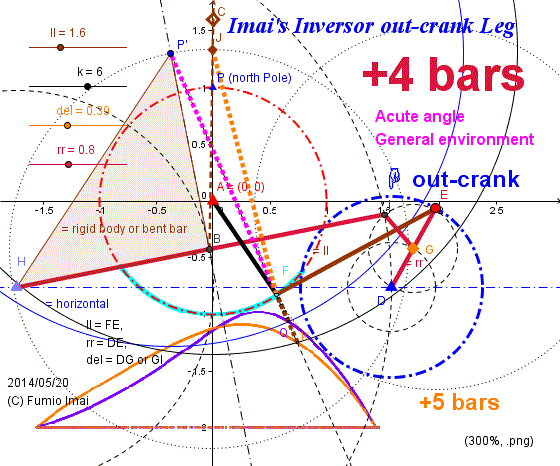
- Centipede_Inversor_out_crank.gif -
- Centipede_Inversor_out_crank.gif -
Imai's hiccup sector Leg
α° circle sector, + α° rotates, and jump, - α° return-rotates. such one-cycle wheel.
Tip: Hoekens Linkage mechanism is similar to the below valve shut/ open control mechanism. they are in same family.
c. somewhat similar shape?
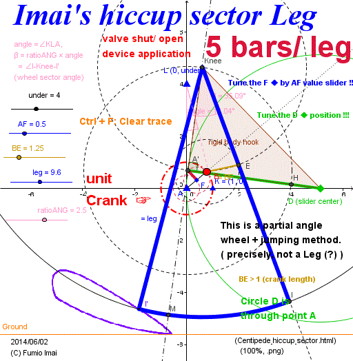
- Centipede_hiccup_sector.gif -
- Centipede_hiccup_sector.gif -
Hart's A-frame hiccup leg sample
Below sample is the Hart's A-frame exact straight line drawer case.
What do think about below figure?
My 1st impression is that
Logic is true, simple, but +5 bars is too expensive.
total 10 bars/ leg is too bad. There are many another methods is 5 bars/ leg.
My personal thinking, if it were more than 7 bars, it's bad method.
In below figure case, can improve ? ----- YES. --- Please deep consider.
------ pending. I'm now reviewing. --- ∵ shape is OK, but angle is bad. Give me more time. ------ conclusion: This idea in Hint is BAD logic [ / not elegant]. original +5 method is recommended.
Hint: point K (or Q) node ---- what trace does it draw? Crescent under half is complete arc, upper half is any. Is there such curve generator in the world?
Chebyshev linkage like family crescent is all so. because outer (/ upper/ roof) arc part of Chebyshev is almost complete arc/ circle curve.
+3 bars is possible [Replace K to the crescent device. and point D fixed. cut DK segment.] . total 8 bars/ leg --- too big, yet.
if you apply crescent, I recommend, same rotation direction crescent should be used.
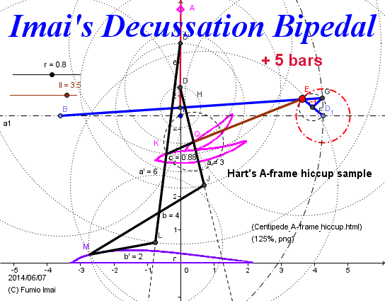
- Centipede_A-frame_hiccup.gif -
- Centipede_A-frame_hiccup.gif -
Here is the Anchor name = "Centipede_crank_amplifier".
2 bars crank amplifier
☞ Someone Please, prove that the below orange curve and Chebyshev Linkage curve are the same group, mathematically. (somewhat Chebyshev has sharp edge-end-angle.)
Musashikogane Leg's stride length is the crank diameter, so large stride needs large crank.
Orthodox amplifier needs many bars. Less bars method are there?
One answer is below Fig. Mapping crank circle to wide flat circle by adding 2 bars.
In below Fig., the crank diameter 2 rr is transferred to (mm) [ex. mm = 2.5] multiplied length, red crank circle was mapped to orange wide flat circle [≒ upper half of ellipse] .
Orange flat circle shape is so similar to the Chebyshev Linkage trace shape.
Point D is vertical slide part. I replaced this part to the long bar arc curve from exact straight line.
(
Many good property than Chebyshev/ Hoekens Linkage curve.
• Comparing this shape to Chebyshev, The height is larger than Chebyshev. i.e. This is thick, Chebyshev is thin.
• This Fig.'s height is always 2 rr [= origin crank diameter] constant (independent from mm value).
• Base edge curve is almost straight as, the smaller arm, the smaller mm. Just straight case ratio is (rr, arm, mm) = (1, 1, 1), (1, 2, 2.5), (1, 3, 4), (1, 4, 5.2?), ....
• Roof curve is always almost just/ complete circle with radius = (mm) rr length.
• At last, I confess that I'd dislike the Hoekens Linkage. Because, the directions of rotation of Crank and Trace are different. This is very bad. not honest. So, I don't like Hoekens.
• Concave, crescent moon shape trace maybe OK(?). [In spite of the crescent orange crank trace, (almost) works well it looks so. And in this case, foot size is zero type leg. very easy implementation.] --- interesting. Tuning is very easy, this system. At least, increasing the stride span is very easy. many tuning parameters are there, this is good. --- Please check.
)
But, layout is not good.
Please tuning the line g (Vertical slidable) [ point G including], set to the position as the most wide orange circle.
Tip: As a result, Chebyshev/ Hoekens Linkage is almost interchangeable with this method. Perhaps.
Exact straight line, it's no needed. it's enough to long long bar arc.
(vertical line slide: Or, it can be replaced by "Watt's linkage" [See. animation] --- more short 3 bars component. )
Hoekens Linkage structure is not symmetry, this is bad from view point of dynamics.
And, in usual in Hoekens system, in order to increase stride span, amplifier 4 bars adding is needed. but, below system no need such 4 bars (m:n proportional division linkage --- I searched by Google dividing linkage, but I couldn't get such geometric picture. poor Google. why?, it's very basic figure. --- Found!!!, 1. THE PANTOGRAPH).
So, Below upper half ellipse generating apparatus is superior to Hoekens.
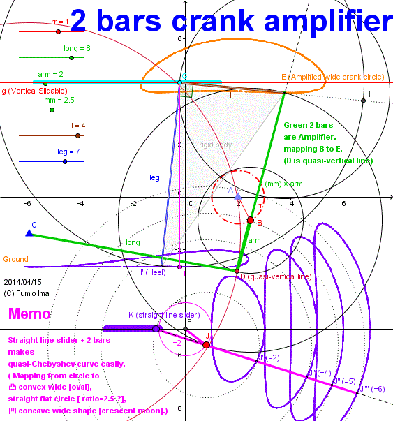
- Centipede_crank_amplifier.gif -
Do you know, AB = BD = BE case?
This is very famous. :
E runs on the X-axis.
(∵ D runs on the Y-axis.)
----------------------
We can set Point C and D( = Base of amplifier/ pivot point) between Point A and E (--- i.e. set as inner point).
In this case, direction of rotation of orange trace becomes reverse relation like as Hoekens Link.
( Chebyshev/ Hoekens curve is sharp & wide than this. different type curve, different efficient mechanism, it looks like so to me.
Witness: Chebyshev case, increasing the apparatus bar length, creates wide flat half moon, and the height decreases. but in the case of the left Fig., the height doesn't change. keeps fatness.
--- I checked deeply.
Result: Chebyshev symmetry curve is special case in reverse rotation mapping type, 2 circles are cross or including relation, and pivot point traces is 45° slider case. Symmetry curve can be made by vertical pivot slider like as the left Fig., and Management is easier vertical pivot type than Chebyshev type. )
- Centipede_crank_amplifier.gif -
Here is the Anchor name = "Centipede_circle_mapping".
Centipede_circle_mapping.gif
Please review Chebyshev/ Hoekens Linkage condition, from the circle mapping view sight.
Input: ● (unit circle)
Middle Media: ▲ circle/ line Slide Pivot point
Output: ■ What curve trace?
i.e. relation: ●(input curve) ― ll length bar ― ▲(pivot curve) ― (mm) ll length bar ― ■(output curve)
(Tip: ▲●■ layout is OK.)
c. I/ we say/ distinguish, Back-end pivot type, Front-end pivot type according to the pivot position.
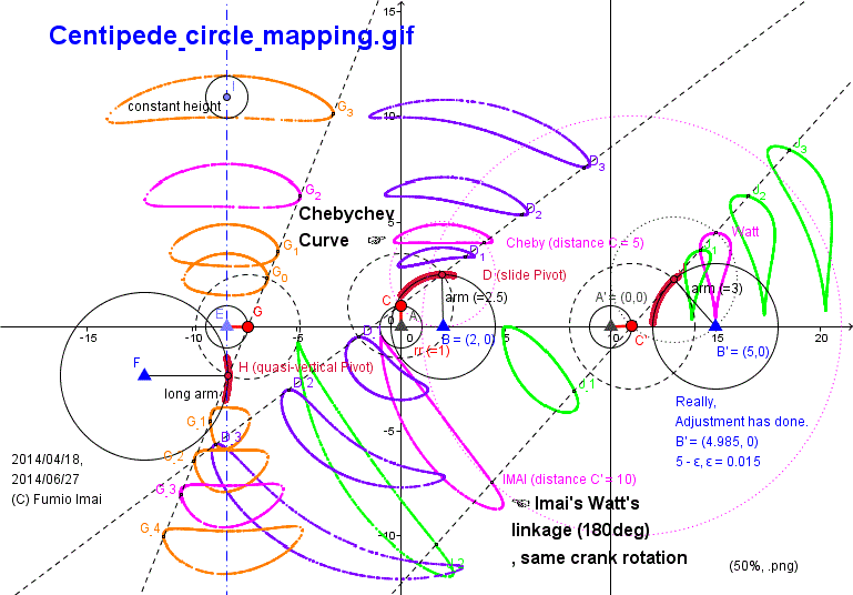
- Centipede_circle_mapping.gif -
Chebyshev flat half moon figure is critical special condition. (?)
Chebyshev Linkage belongs to the Front-end pivot slider type, so, direction of crank rotation is opposite to the result. (i.e. has the reverse direction.)
and Chebyshev case, the slide angle is slant/ inclined (about 45°), so the angle bias/ unbalance occured. i.e. the bottom edge most left and most right position is not corresponding to crank x, x+180° angle. gap is more 180° --- this property is important for bipedal system. therefore, 2 legs can tangent the ground at same time. --- and quick return stroke is achieved.
Imai's Watt's linkage (180°) has quick return stroke as Chebyshev.
i.e. Imai's Watt's linkage (180°) is almost the non-reserve rotation version of Chebyshev linkage.
This linkage details is in below section.
cf. Goto jump: Imai's Watt's linkage Vertical Leg (180° cycle)
- Centipede_circle_mapping.gif -
Here is the Anchor name = "Centipede_Cheby_45_slide_length".
Slider Curve-mapping Length law
Line slider mapping from arc (estimated radius = r circle) to straight segment by arm1, arm2 input-side/ output-side length bar. What relations in the length?
arm2 = f(r,arm1) = r (sqrt(r2+arm12) - r) / (sqrt(r2+arm12) - arm1)
or
= (1/r) (sqrt(r2+arm12) - r) (sqrt(r2+arm12) + arm1)
c. Case of big arm1 >> r, then, arm2 ≒ (1/r) arm1*(arm1+arm1) = 2 (1/r) arm12 --- i.e. arm2 ∽ arm12
---- So, we can use this apparatus as the amplifier.
c. Front-end pivot slider type; i.e. object shape ---arm2--- pivot ----arm1 --- input shape,
This is the case of Chebyshev Linkage type, --- from my investigation, arm2 length estimation formula※ is given as next.
arm2 = f(r,arm1) ≒ [ r (sqrt(r2+arm12) - r) / (sqrt(r2+arm12) - arm1) ] - arm1
(almost the same Back-end type formula except offset part, - arm1.)
※; To confess my mind, this estimation is difficult. I can't agree/ satisfy this result. real value looks like somewhat smaller than this estimation.
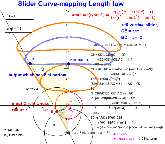
- Centipede_Cheby_45_slide_length.gif -
arm2 = r (CV/AW)
- Centipede_Cheby_45_slide_length.gif -
Here is the Anchor name = "Centipede__45degree".
45 degree slider Amplifier
How to make the walking leg trace by smallest linkage bars?
Chebyshev/ Hoekens linkage trace shape is good and the smallest number of bars, but its layout position is above the crank. So, we must shift the position to under the crank. Much bars are needed. This is the bad matter. Breaking the simplicity.
My heuristic answer is below.
Remark: ------- But, crescent circle is Chebyshev/ Hoekens is OK, vertical slider type is NG. Because, vertical slider type crescent has a crank angle problem which 2 legs can't keep horizontal body. i.e. When one leg comes on turning point, the other leg is yet in return stroke. So, at least 3 legs are needed to keep body horizontal. --- like a Theo Jansen leg.
Chebyshev type linkage has not such problem. Because, return stroke crank angle span (< 180°) is smaller than outward stroke angle span (> 180°). ---- like a Klann linkage leg. (but Klann leg trace is for a walking spider. Human walking trace shape is more smooth.)
below describes
(1) from unit red crank circle to orange crescent circle by vertical slider amplifier (Chebyshev linkage type crescent).
[ Below figure, I dare remain the old figure. for education.]
(2) from orange circle to blue leg trace circle by 45° slider amplifier.
i.e. 2-tier mapping has done.
• keeps same rotation direction. size is amplified. position is moved to lower.
• 2 coupler bars and 2 quasi-line-slider realized by long bars (= it's enough by somewhat long.), total 4 bars apparatus.
----- brown color curve is a finite long bar sample.
Tip: Ideal angle of HI is perhaps 30°. Is always so? Someone, check this, please.
Tip: We can execute the orange to green mapping, but this case flat shape output position is not under the crank. very pity※. Green mapping is attractive for keeping a symmetric figure feature. Therefore, if 0° mapping is available, we should use it, and when it's not available, we can use the 45° strategy.
45° mapping has a property of rotation and prolong the output position.
Note ※: To tell a truth, we can break this difficulty. It's very easy. Its answer is to increase the arm3 value.
Tip: In a nutshell,
±45° method is like a Fosbury Flop in high jump. Or, is like a Limbo (dance) technique.
0° method makes 〇 to 〇 symmetry shape, ±45° method makes 〇 to ◢ unbalanced shape over there/ opposite side.
----- i.e. 0° technique can't (/ is difficult to) clear the high jump bar. ≒≒≒ can't be over the crank position.
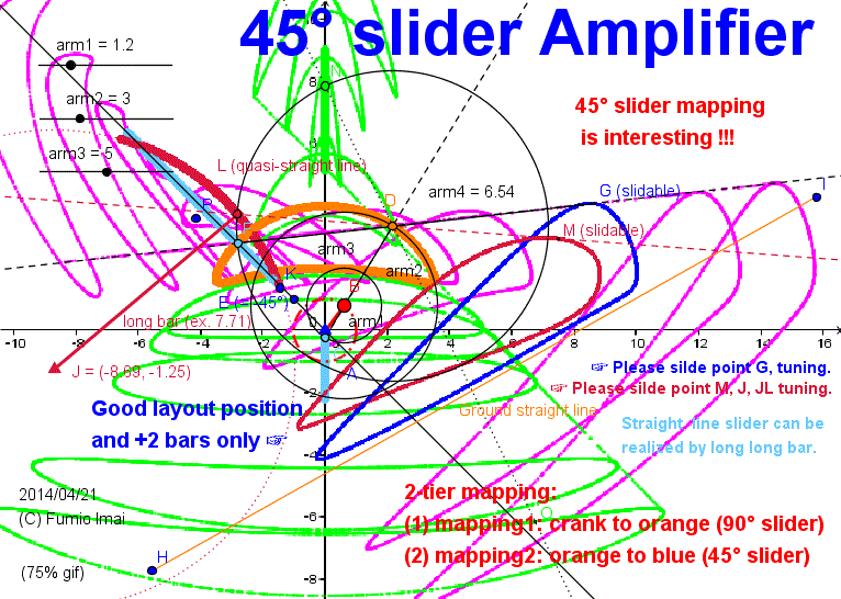
- Centipede_45degree.gif -
- Centipede_45degree.gif -
-----------------------------------------------------
Here is the Anchor name = "Centipede_Cheby_45_slide".
Chebyshev-crescent-45 degree-slide-mapping
Evidence of above my hypothesis. --- Chebyshev crescent moon mapping result Sample.
There are 2 type Chebyshev crescent. One crescent is before phase shape of usual complete flat full moon. The other crescent is after phase shape.
Below sample is after type. large leg type.
Before phase crescent is possible, too, of course. Please try.
cf. Orthodox Chebyshev linkage (3 bars) + Pantagraph/ Pantograph (4 bars) [ sum 7 bars/ leg ] system.
• Design and Analysis of a Low Cost And Easy Operated Leg
Mechanism For A Walking Robot. (.pdf) on 2012
(My comment: 4 is > 3. [ i.e. additional parts is more than core parts.] ---- This apparatus is odd [= expensive enough], for me. --- not clever.)
• Design and Optimization of Plannar Leg Mechanisms Featuring Symmetrical Foot-Point Paths (.pdf) by (c) Win-Bin Shieh 1996
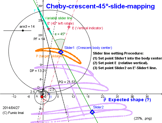
- Centipede_Cheby_45_slide.gif -
Left shows how to tuning.
By using this mechanism,
we can make a compact Chebyshev type leg.
(The leg/ foot is located under the crank.)
i.e. 3 bars + 2 bars = 5 bars/ leg.
(here, exact straight slider is implemented by a long bar arc. --- i.e. quasi-linear.)
There exists a God. I think so.
Tip: 45° Front-end slider can exist, too.
Angle 0° method can exist, but Back-end slider only. 0° Front-end slider can't exist.
- Centipede_Cheby_45_slide.gif -
Here is the Anchor name = "Centipede_Cheby_45_slide_small".
5 bars Chebyshev Leg (small span)
Evidence of small span type crescent moon mapping.
In below Fig. 2 legs figure is described.
The bottom of leg/ foot trace is somewhat curved (= not straight line), but it's affordable, perhaps. ---- This is a cheap price apparatus.
c. Someone, Please make a walking bicycle by this. Merit = simple structure. Demerit = crank rotation is reverse to the leg rotation.
Enjoy the DEMO.
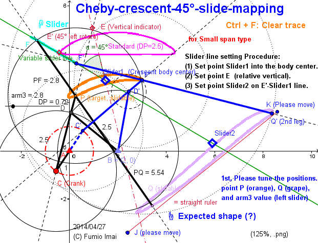
- Centipede_Cheby_45_slide_small.gif -
Left shows how to tuning.
Why orange slug's head-tail direction is reverse/ opposite to the plum slug's ones?
(cf. In below + 45° case [in almost the same circumstance], --- the same head-tail direction.)
Slider1 is set to the middle of the bottom arc surface. somewhat left is OK, too. Please check.
- Centipede_Cheby_45_slide_small.gif -
Here is the Anchor name = "Centipede_Cheby_45_slide_best".
5 bars Chebyshev Leg (2 tier mapping model)
--- Hypothesis
I learn the property of My 5 bars Chebyshev leg from try & error by GeoGebra tool.
It seems there exist a beautiful rule.
Below Fig. is the best result of it.
(1) Line slider angle is y=x absolute 45°, perhaps.
( Absolute -45° also is good (case by case?). both good. so, please try to check both. )
( And further, Please check relative ±45° case. there exists relative 45 is better than abs 45.)
---- WHERE is the truth?
My official answer: Output shape depends on the input bottom curve shape and slider angle. If input bottom curve is honest, I recommend to apply 45° or 0° angle slider. Relative 45°/0° angle method is better than absolute angle method, theoretically. If absolute angle result were better, it was by chance (total(/ not local) result by many influenced elements condition effect). --- i.e. local optimization is not total optimization in general. local or total criteria is difficult.
(2) This is a pure mathematical (theoretical) problem. Geometric mapping property problem.
ex. Horizontal Chebyshev flat full moon is transferred to vertical dropping water shape (where, bottom is straight flat) .
---- Someone/ mathematician , please prove or study this hypothesis/ property.
-- I found the next item in Klann Leg site.
~This is a flash animation of one possible configuration of the Klann linkage. The mechanism is an expansion of Burmester theory that converts rotary motion of the crank to linear movement of the foot for one-half rotation of the crank and raises the foot for the second half, returning it to the starting point. Two of these linkages, 180 degrees out of phase, will function as a wheel replacement.~
----- That is, Theory which I wanted/ needed, maybe the "Burmester theory" (?). But, wikipedia explanation is too difficult to read. I'm novice. bad.
----- I think, To tell a easy thing as a un-easy/ difficult thing, ----- this is a bad thing.
c. Please tell me the website of Burmester theory to study. I couldn't find such page.
cf. Ludwig Ernst Hans Burmester (5 May 1840 ? 20 April 1927) was a German kinematician and geometer.
|---- cf. The pronunciation of "burmester" (IPA)
|---- The CMU Pronouncing Dictionary : Burmester / B ER M IH S T ER /
(3) Direction of Leg trace rotation and the crank rotation can be the same direction. --- i.e. by lever tool. Using the Front-end slider.
(Chebyshev Linkage parts is a Front-end slider type, so the leg rotates reverse direction. If adding the next front-end type slider, the leg rounds as crank. i.e. (-1)*(-1) = (+1) result.)
Tip: In above (1 before/ previous) Fig. last figure's bottom was somewhat curved, but below Fig. bottom is almost flat. So, perhaps Absolute 45° mapping is true. --- case by case is true.
c. Chebyshev shape = f(circle), ----- Chebyshev like flat bottom shape = f2(f1(circle)) There exists such f1, f2 mathematical function. 2 -tier. including a changing position. f1(circle) = crescent [= concave], f= f1 * f2, Circle arc + straight line slider makes flat bottom. 45° bias effect. etc.....
f or f1 or f2 is function/ operator/ pivot/ converter/ mapping. In this apparatus, it's a line slider or circle slider as pivot.
[ ex. Chebyshev linkage case [ --- big category: convex 凸 to cocnave 凹 mapping]:
input: A(0,0) r=1 circle
pivot slider: B(2,0) r=2.5 circle ( ---- This pivot is front-end type, so the reverse happens.)
(from big sight-view, this is belong to 45° slider family(?))
input arm: arm1=2.5, output arm: arm2=2.5
output: Chebyshev flat halfmoon shape, bottom is almost flat, wide length≒4 ]
As of 2014/04/28, by © Fumio Imai.
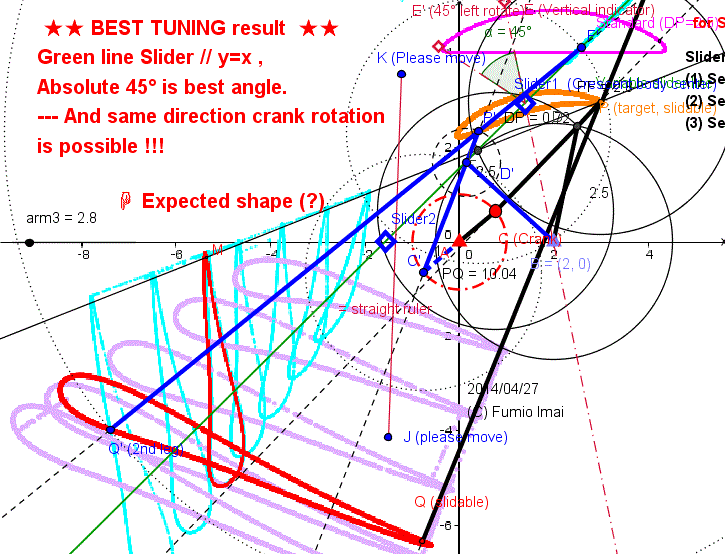
- Centipede_Cheby_45_slide_best.gif -
Red figure shape is great.
Vertical dropping water figure is gotten by Slider position changing.
i.e. Locates after the point P. i.e. reverse mapping.
i.e. Back-end type slider: same rotation.
Front-end type slider: reverse direction.
(reverse case: amplified ratio becomes down.)
Tip: Angle 0° method can exist, but Back-end slider only. Front-end slider can't exist.
So, 45° Front-end type is very special/ valuable.
- Centipede_Cheby_45_slide_best.gif -
----------------------------------------
Here is the Anchor name = "Centipede_Cheby_45_slide_quasit".
5 bars Chebyshev Leg (quasi-linear)
Below shows the quasi-linear slider sample.
Tip: There exists a experimental rule.
(a) The point F is between D and E(= Chebyshev standard shape).
(a-1) If F is near E, result I is near F.
and I's width is bigger corresponding to the distance from E.
One example, if E is input , then E is output. --- This is typical good sample.
Tip: It's not difficult to find the circle slider [ Back-end/ Front-end both type] which makes almost flat bottom shape output under the crank.
I don't know the theory yet, but it's easy to find the satisfying samples.
sample value list:
(1) arm2= 1.19 (small type), Back-end circle slider center (7.65,3.17) r=5.74, arm3_b=4.8,arm4_b=5.38
(2) arm2= 1.19, Front-end circle slider center (-2.97,2.4) r=3.54, arm3_f=3, arm4_f=3.23
(3) arm2= 7.2 (big type), Back-end circle slider center (-3.6,5.51) r=8.73, arm3_b=5. arm4_b=11.23
(4) arm2= 7.2 (big type), Front-end circle slider center (9.41,6.53) r=7.34, arm3_f=6.8, arm4_f=6.23 --- like a Klann shape [Right triangle shape], but this is the same direction as crank --- is not a human walk
( big-type & Front-end & human walk --- there doesn't exist this type).
c. Klann or Jansen shape is only a one of them in this crescent moon changing model system. I think so.
--- You are a witness. Please see below DEMO (13-d)
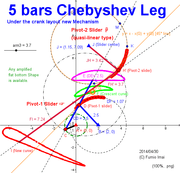
- Centipede_Cheby_45_slide_quasi.gif -
Finite radius circle quasi-linear approximation.
Result new curve I has enough flat bottom, I think so.
Which is true, this slider must be linear or circle theoretically?
This 2nd slider is not leaner, circle, but result is almost good.
( At least, 1st. slider is circle [r=2.5,B(2,0)], so, 2nd is also circle is true? ---- Please, Someone, check [i.e. ideal slider is linear?, or circle?, which is true? ] & prove !!! )
c. I searched Slider-2 radius JH=2.5 case (other length parameters are all the same.); I found J(1.15,7.54) is answer. I trace shape is almost the same as left fugure. But, slider part is not on the y=x-x(G)+y(G) line. but slide line angle is about 45° (offset part is different). So, 45° hypothesis is true.
[ J center position change search by carpet bombing/ all grid points. --- I did. be tired.]
This figure looks like a somewhat symmetry structure in upper/ lower part relation.
Q: Why? A: I made so.
- Centipede_Cheby_45_slide_quasi.gif -
Here is the Anchor name = "Centipede_Cheby_45_slide_symmetry".
Find Symmetric bottom crescent !!!
Most easy implementation is, to find a symmetric bottom crescent. and Apply 0° line angle slider.
--- We can get the symmetric leg trace system.
(The activity to find a symmetric bottom crescent is not hard. I think so.)
(There are numerous symmetric bottom crescent.)
Klann linkage, Jansen's linkage --- These are the name after originator's person's name.
So, I want to name the this apparatus after my name officially. As below.
Imai's linkage (alias, Crescent mapping leg.)
My comment: Leg linkage design is not hard at all. Using 2-tier mapping from arc to straight segment technique, it's easy thing.
I think Klann Linkage does not deserve the patent. 2-tier mapping technique is general evident truth. From the view point of 2-tier mapping, the Klann shape is not special curve or technique at all.
c. How to get symmetric srecent linkage?
cf. Symmetrical Coupler Curves (YouTube)
Related: Coupler Curves Intro (YouTube), Path optimization (YouTube), Graphical Linkage Synthesis Chapter 3
MECH324 - Homework Hints, Answers, and Extra Requirements (©MECH324
Dynamics of Machines; by Colorado State University)
|-- FIGURE 3-16 A "Cursory catalog" of coupler curve shapes --- name list included
• Symmetrical shapes:
|-- FIGURE 3-21 (a) Variation of coupler curve shape with common link ratio and coupler angle for a ground link ratio L1/L2 = 2.0
|-- FIGURE 3-21 (b) Variation of coupler curve shape with common link ratio and coupler angle for a ground link ratio L3/L2~ = 2.5
c. Easel type carrier, is easily possible.
Easel is the same shape as below linkage. So, imagine !!!, Put the travel-bag on the side of the easel, and let/ have the easel walking. ---- this is possible. i.e. a walking easel.
( This leg always stands on both feet with a probability of 75% [= 270°/360°]. )
----See, the concrete sample image of Walking Easel from below DEMO Link.
(13-g) Imai's linkage (tri-pedal) (alias: walking easel) (3 legs can be colinear. 2 legs are always on the ground.)
[ Chebyshev linkage (tri-pedal) case can't be colinear with 3 legs. i.e. only one leg on the ground timing exists. So, In tri-pedal case, Imai's linkage method is better/ more stable than Chebyshev linkage. ]
cf. Continuous track (wikipedia) ---- Imai's linkage (tri-pedal) has this property.
---- By this, we can make a bicycle running on the sand of seashore. (?) --- Like a camel in the desert.
c. 2 foot J(1st), J'(2nd) both touching the ground at same time, in this case the distance between J and J' is almost constant, below Fig. case, stride ≒ 11 [7-(-4)=11],
|x(J)-x(J')| = from 7.5 to 8.0 value range. error =8.0-7.5 = 0.5 order. [i.e. 0.5/11 = 5% order ]. slip friction happens, but is negligible. (?)
----- This defect can be avoid.
i.e. In order to avoid the foot slip, I propose the flexible between angle crank.
ex. Each crank bars are separated by cushion spring. ---- cushion/ lag technique.
i.e. (bipedal: ≒ 180° angle [ = 180° ± α ]) or (tri-pedal: ≒120° angle)
(This leg is the foot driven type [= not motor driven leg], so foot interval distance is a master, crank bar interval angle is a slave. )
c. This apparatus is simpler than Imai's Hart's A-frame 5.5 Leg, so non-stop walking stand-alone apparatus is possible. But there is no one leg standing mechanism. if 2 legs in a row connection style is easy solution, but this is not stand-alone style. So, I think that, the compromising solution is tri-pedal.
120°+120°+120° tri-crank Leg, long long leg, please to challenge the GUINNESS BOOK records.
Q: tri-pedal is not worth to Guinness book? --- A: I don't think so. because,
Passive Walking Robot Propelled By It's Own Weight (by Nagoya Institute of Technology )
is in a precise sense 4 legs apparatus (2+2 wide/ widthwise), not 2 legs. So, 3 legs(1+1+1 wide/ widthwise) is allowable.
Further, 3 is < 4. (beings more compact style).
☞ Someone, Please make this tri-pedal Leg,
and Challenge the Guinness book records (non-stop walking) !!!.
please realize/ achieve 1 years no-stop. It's so easy thing. ------- See DEMO (13-g) from below GeoGebra DEMO Link ☟.
(---- The 3rd leg moves like a pendulum.)
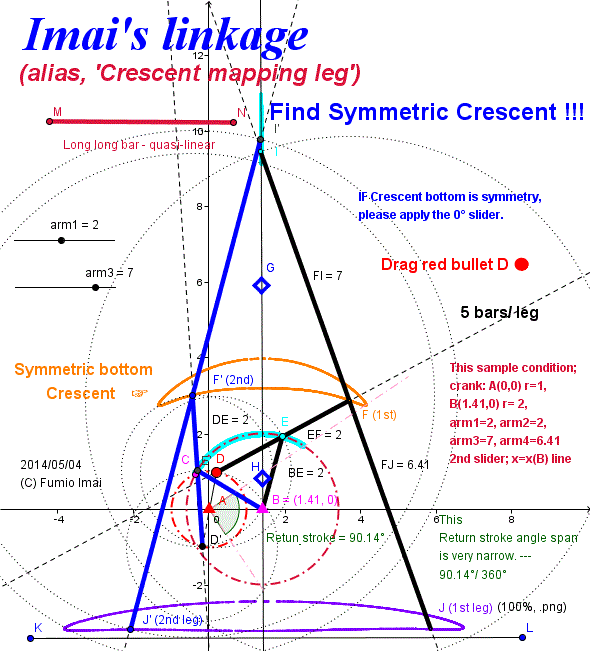
- Centipede_Cheby_45_slide_symmetry.gif -
This is the most general & simple concept solution (than Chebyshev standard Linkage), I think so.
ex. Symmetric crescent shape is more general than flat half moon shape.
--------------------
In left sample case, crank 75% angle is in forward stroke process, so one or two of 2 legs is/ are always touching the ground. This is good property.
So, no motor driven, hand pushing/ pulling cart is possible by this.
i.e. In spite of no motor, the crank can rotate smoothly.
cf. Leg style carrier (VTR) (© Nagoya Institute of Technology in Japan)
--------------------
Q: What do you feel from left figure?
My sample A: I felt that the crescent bottom curve is regarded as a ELLIPSE curve approximation.
(Check of your mathematical sense, --- from me.)
Because, Point J runs on X-axis and point I runs on Y-axis, and Point F (which is the internal division point of IJ, arm3 vs. arm4 ratio) runs on crescent bottom curve.
If so, this curve must be ellipse.
---- So, More precise expression is "Find ellipse curved crescent !!!". I thought so.
but, from result arm3=7, arm4=6.41 --- almost arm3≒arm4, OH, almost circle.
c. I tried to search the small INTEGER ratio environment, I compromised this result. B(1.41,0) is near (√2 [=1.41421356 ※], 0) (?). if so, this sample result is all 2 relatives.
Much much better another environment are there whose value isn't integer.
B(√2, 0) estimation is very, very good value.
ex. when D(1,0) --- F is on just middle of roof arc (√2, 3.98) , D(-1,0) --- F is on just middle of bottom arc (√2, 3.19) [where, 3.19 = sqrt(13-2sqrt(2)) ] . F most left is (-1.32,2.74) , F most right is (4.16,2.74) same Y-value, width =5.48. D(0,1) --- F(3.5,2.94) [where, 3.5 = sqrt(2) + sqrt(13/3), ], D(0,-1) --- F(-0.67,2.94) same Y-value [where, -0.67 = sqrt(2) - sqrt(13/3), 2.94 = sqrt((29+2sqrt(78))/3)-1 ---(= sqrt(26/3) --- what is this? why sqrt((29+2sqrt(78))/3)-1 = sqrt(26/3) ??? Nested radical )].
ex. x=(1/2)(sqrt(2)+1/sqrt(2)) = 1.060660172---- = (3/4)sqrt(2) = 1.060660172,,, magic?, difficult!!
ex2. sq((29+2sq(78))/3)-1
=sq((29+2sq(3*2*13))/3)-1
=sq(29/3+2sq(2*13/3))-1
=sq(29/3+2sq(26/3))-1 [here, 29/3=1+26/3]
=sq((1+sq(26/3))^)-1
=(1+sq(26/3))-1=sq(26/3)
Tip: Crank circle A and Crescent moon figure are in symmetric mapping relation each other.
i.e. Circle A +y, -y symmetry is corresponding to Crescent moon -x (=left hand), +x (=right hand) [here, x = sqrt(2) is center line symmetric line] symmetry precisely.
i.e. Circle A and Crescent are converted by y=-x line (- 45° line) .
c. Crescent curve: f(x,y) = 0 equation function, if so, f(sqrt(2)-x, y) = f(sqrt(2)+x, -y) is always true. ---- Please, prove.
c. Suppose Circle A : x^+y^=1 , Crescent: (X,Y), if So, next equation is true (= satisfies next). [ in above fig. D(x,y), F(X,Y), E(0.5(X+x),0.5(Y+y)) ]
• (√2,0) 2 circle is a middle point of Circle A and Crescent, so,
[0.5(X+x)-√2]^+[0.5(Y+y)]^=2^ i.e. [(X+x)-2√2]^+[Y+y]^=4^ --- ①
• length 4 bar, So, (X-x)^+(Y-y)^=4^ --- ②
From ①, ② we can get X,Y.
① - ② = 0; Y=(√2-x)(X-√2)/y ----- ③ ---- this indicates, Y=(√2-x)(-X+√2)/(-y) --- So, Crescent is X=√2 line symmetry. (Remark) † (∵ (x,y) to (√2-X,Y) mapping, (x,-y) to (-(√2-X),Y) mapping has the same Y.)
(if so, in above fig. Return_stroke = 90.14° description is wrong. real angle span is more smaller than this. and ± symmetric angle figure.)
X is next quadratic equation solutions.
[y^+(x-√2)^]X^-2√2[y^+(x-√2)^]X+[y^^+{(x-√2)^ -14)}y^+2(x-√2)^]=0 --- ④
(④ indicates, depends on y^, so +y, -y is indifferent.)
X^-2√2X+[y^^+{(x-√2)^ -14)}y^+2(x-√2)^]/[y^+(x-√2)^] = (X-√2)^ -2 +[y^^+{(x-√2)^ -14)}y^+2(x-√2)^]/[y^+(x-√2)^] =0
So, X=√2 + sqrt(2- [y^^+{(x-√2)^ -14)}y^+2(x-√2)^]/[y^+(x-√2)^] ) = √2 ± sqrt(y^[-1 + 16/[y^+(x-√2)^]] )
So, x^+y^=1 apply, then --- X= √2 ± sqrt((1-x^)[-1 + 16/(3-2√2x)] ) --- ⑤
test: x=0 case; X= √2 ± sqrt((1-0^)[-1 + 16/(3-2√2*0)] ) =√2 ±sqrt(-1+16/3)=√2 ± sqrt(13/3) -- oh! valid value!
test: x=+-1 case; X = √2 ± sqrt(0) = √2 --- true!, then Y = sqrt(13 +- 2√2 ) ---true. (not available ③)
----
----
Please find theoretical arm3 (now =7), arm4 (now =6.41) value. [ arm4 = 6.0 is better than 6.41 ? --- YES. ]
[ arm3 = 7.0, arm4 = 6.0 (all INTEGER) is the best.
ex. in tri-pedal case; when D(-1,0) case, 3 legs are colinear and each y value is the same -2.81, i.e. all on the ground with no height gap.
but bottom line total has a up-down wave; y = -2.8107(=left) to -2.7752 to -2.8107(=center) to -2.7752 to -2.8107(=right) [gap 0.0355] in stride x span 11. [error rate: 0.035/11 = 0.32%], lowest 3 points are corresponding to -180°, -180±120° 3 points. ---- (-2.81 is near -2√2 ?), ----- these 3 points are local minimum.
Chebyshev linkage case; y = 4.0000(=left) to 4.0098 to 4.0000(=center) to 4.0098 to 4.0000(=right) [gap 0.0098] in stride x span 4 [error rate: 0.0098/4 = 0.25%] --- has the same error order (?) and same up-down wave trend. lowest 3 points [= local minimum] are corresponding to -180°, -180±90° 3 points. and -180±120° point are corresponding the most left/ right point y= 4.062 [gap 0.0620] , So, angle trend is different. Chebyshev is fit to 4-pedal. And, Imai's is fit to tri-pedal.
Chebyshev case 120° is already in return stroke mode. but Imai's Crescent case 120° is in forward stroke mode yet.
--- as of 2014/06/10 Fumio Imai. ]
(Remark) † : symmetry property is generalized as below
• center B(a, 0) radius b circle [(x-a)^+y^=b^] is a middle point of Circle A and Crescent coupler/ bridge bar, and radius b length is the same as half coupler bar length.
i.e. (1/2(X+x)-a)^+(1/2(Y+y))^=b^ ---- eq.ⓐ
then ((X+x)-2a)^+((Y+y))^=(2b)^ --- eq.ⓐ'
(X-x)^+(Y-y)^=(2b)^ --- eq.ⓑ
(2X-2a)(2x-2a) +(2Y)(2y)=0, So, (X-a)(x-a)+Yy=0 ---- Y = (X-a)(x-a)/ y ----- eq.ⓒ
So, arbitrary center (a, 0) radius b circle ensures the symmetry property.
i.e. when x^+y^=1 is the crank and center (a, 0) radius b circle is middle point of arm from crank to objective trace node.
then, Crescent moon (or other shape) mapping image is (always) X = a line symmetric. (not dependent to b length.)
(√2,0) radius 2 circle is only a one typical crescent sample. it's just the tip of the iceberg.
Also, (2,0) radius 2.5 circle of Chebyshev Linkage for approximation of line drawing is a tip of iceberg. Many other ratio value set exists.
c. eq.ⓒ also indicates "Vector (x-a, y) inner product Vector (X-a,Y) = zero." i.e. 2 vector are in ⊥ relation. tanθ = -1/tanΘ; ,,,, ∠ABF = ∠ABD + 90°, So, point F most right point is corresponding to point D which BD is tangent to th circle A case [--- = returning point, angle summit point.] .
So, return stroke narrow crank angle is corresponding to this tangent +- angle.
i.e. center B(a, 0) value is quick return velocity barometer. i.e distance |a-1| is smaller is tangent angle is smaller, ----- So, if you want to achieve the more quick return, set value |a-1| smaller. ---- this is important.
My Crescent shape case B(√2, 0), Chebyshev Linkage case B(2,1) , so, √2 < 2 then My crescent Linkage achieve more quick return than Chebyshev.
[ witness; Chebyshev B(2,0) circle case: AB=2, tangent AD=1, ∠ADB = 90°, then angle is ∠BAD = 60° (∵ cosθ=1/2), so +- sum is 120° -- so, forward span: return span = 240:120=2:1 (i.e. 2 times fast)
B(√2, 0) circle case; cosθ=1/√2 --- ∠BAD = 45° so +-sum 90° -- so, forward span: return span = 270:90=3:1 (i.e. 3 times fast) ]
-----------------------------------
Here is the Anchor name = "Cheby_sym_mapping".
(quasi) Vertical straight line slider doesn't need long long radius bar.
In above Fig. Vertical slider is realized long long ∞ length bar (i.e. radius = ∞ 's circle's arc.), it's approximated by long radius long bar. --- I called this result line as "quasi linear".
In general this is true. but, above Imai's Linkage case, short radius is OK, I found by experience/ test.
Why? Short is ok. ----- I can explain its reason now.
This trick comes from the analogy of above section, +- y symmetry (input circle)--- black-box mapping (by constrained linking bar)--- +- X symmetry (output).
The same principle occured, black-box is a circle, middle of linking bar is on circle, and radius length = 0.5 linking bar.
input is MN bar circle. FI ≒ FJ, and crescent bottom curve is ≒ FJ radius circle (this environment is the same as before section story.), output is Leg trace point J.
So, Even short MN ensures output x symmetry. So, MN is short is OK.
----- See the DEMO, and change the length MN by yourself. and get feeling. MN = 2 is OK, MN = 1 NG ( too short).
(my explain might be mistaken. but, short MN is OK. this is FACT.)
This is related Watt's Linkage.
cf.
Robotic Mechanisms Linkages ? Watts Straight Line 51016
Watt's Linkage is equivalent to Evans Linkage.
cf. Robotic Mechanisms ? Linkages ? Evans Straight Line 51013
cf. Chapter 3 Linkage Synthesis ( famous linkage) ( (C) Mechanism Simulation in a Multimedia Environment )
I've inspired/ ignited the new leg method/ idea. 3 bars/ leg ----- perhaps,
The smallest number of bars Leg linkage system (in the world) (?).
(2 straight bars (crank bar, r length bar) + 1 bent bar ( 2r length bar + foot part); half Lemniscate curve trace shape. )
---- Please check.
cf. Optimization of Watt's Six-bar
Linkage to Generate Straight
and Parallel Leg Motion
(.pdf, (C) Hamid Mehdigholi and Saeed Akbarnejad @2012) --- Figure. 10. d) is good. but, orthodox (? -- somewhat, yes.).
|--- BYU - Idaho ME: Walking Mechanism with Straight and Parallel Leg (Youtube)
My comment: Figure. 10. d) is 5 bars/ vertical leg. this is considerable good. 2 legs are 10 bars. --- excellent.
This is superior to my Imai's Linkage (tri-pedal). Because less number of bar, 10 < 15. and perhaps, less slipping. simplicity and robustness comparison needs the real apparatus test.
Imai's Watt's linkage Leg (3 bars/ Leg)
--- Why exists Arches of the foot? ---
I found the reason the existence of Arches of the foot.
Bi-pedal system needs such shape foot. For return stroke support, 180° span angle of crank needs for forward/ return stroke, but 120° span is easily achieved by simple foot shape, more 60° end phase of forward stroke (this 60° phase is lift mode ?) are needed a special shape foot, i.e. toe part are needed. and the area between the heel and the toe is flat or 凹 or hollow shape is allowable. (ex. in below Fig., between tF and F' area is hollow is ok. size zero is ok, of course.)
Below Leg model of linkage is the most primitive/ basic style 3 bars/ leg. this model teaches that such fact.
( Please try DEMO, and feel this fact. please try your design of foot.)
c. Condition, segment length BA = 2r - long, is satisfied. ∵ at crank angle = 0°, G1 mapping to A (G'1).
c. Why the lift mode foot bottom is such wide? almost stride size. too big. it's bad.
foot length ≒ leg stride . ----⇒ this is not a leg, isn't it? ,,, similar to a roller, wheel??
Someone, please tell me why.
Q: This odd leg is useful, ??? --- A: as, low height large radius wheel.
------- Anyway, if dislike this, apply the 120°-120°-120° tri-crank, tri-pedal/ set. i.e. 9 bars/ set.
---- sufficient it is!
cf. related site: 佐藤ロボット研究所不定期日誌 (Language is in Japanese, @2008) --- see 2 animations (Please Click the figures in page, animation will be spawn.).
c. This apparatus foot curve was approximated by a complete circle arc. it was easy work to find the best fit curve. Because, most easy curve is circle, and it looks very very good curve.
Someone, please prove that " the best fit curve of this apparatus is circle (?).".
→ This hypothesis is true. I can prove.
Please check of the trace of center of this fit large circle in DEMO. its trace is drawing the horizontal line. So, this hypothesis is true.
this large circle radius length depens on the "r, long, AB =2r - long" relations.
Chebyshev linkage case "r= 2.5 long, long, AB = 2r-long= ignore = 2 long", large fit circle is not needed.
Further, this large circle center trace rotates the same rotaton direction of crank. and diffrent angle tuning has symmetric trace curve, like a chebyshev curve, but rotion is same sa crank.
So, this trace curve mechnism is superior to Chebyshev mechanism. I think so. This is related to the story of 45° angle shift mechanism previous described.
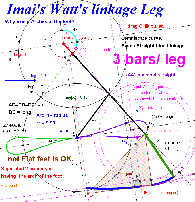
- Centipede_Watt.gif -
bold bars only.
AA' part of trace is almost straight curve. but BC radius ▲―● is short.
Orthogonal dashed line ( ― - ― - ― - ) is symmetric line of input and output figure.
( Mapping from Gi to G'i [ i = 1 to 4 ] )
This is related to "
Y-axis slide mapping to X-axis slide by mediator circle x2 + y2 = r2 : --- Scott Russell linkage. ".
• leg stroke under the crank. --- good.
• but, forward interval span angle is about 120° --- bad/ small.
(at least 3 legs needs to walk.)
I tried 120° up to 180° by adding improved foot. Then , I found that foot shape has the arch of the foot.
i.e. This foot is not Flat feet.
---- This is very intersting.
- Centipede_Watt.gif -
-------------------------------------
Imai's Watt's linkage Leg walking Toy on the slope
I designed a below bi-pedal apparatus. flat feet (distance between tF and F' is zero).
Please make below toy (if possible), and challenge the GUINNESS Book non-stop records.
Pink ball ● is a heavy ball and is rolling on the foot plate. generates unbalance state. Switch/ transfer to another foot at the time of both feet exchanging.
A kind of The Tumbling Toy.
What's the meaning as foot size > stride size ?
slip occurs? --- No. and, moved distance is just stride [= x(G'3)-x(A) ].
A'G'3 curve is achieved by tF-I' long curve bar rolling result.
feeling: stride = length of tF-I' curve.
quick speed: ( tF-I') / [( tF-I')-(AA')] times velocity.
Tip: Low energy tuning;
From a view point one leg to other leg, forward stroke leg lifts a other leg by tops arm CC'2 ( length = 2*long ), moves angle from 0° to 180° + ∠G3AG'3, and other leg is in hanging state.
So, this energy of lifting is not little, in order to decrease this energy, set short the length arm bar. i.e. long is short is low energy consuming.
Who lifts arm ? ---- line of (AB - angle2) is vertical is implicit condition.
( Gravity makes effect/ effort to become vertical. ? )
Changing the point of view is needed.
Conclusion (?):
in order to ensure AB line vertical, I recommend to use 4 long toe legs system, i.e. 90°-90°-90°-90° crank system. 2 legs always on the ground, so AB is vertical. total 3*4 = 12 bars/ system. but structure is simple. one leg is light ( not heavy). perhaps, better than Chebyshev 2 vertical legs 5*2=10 bars/ system.
(Groud slip problem will occur? --- Can't imagine. Needs check by DEMO. )
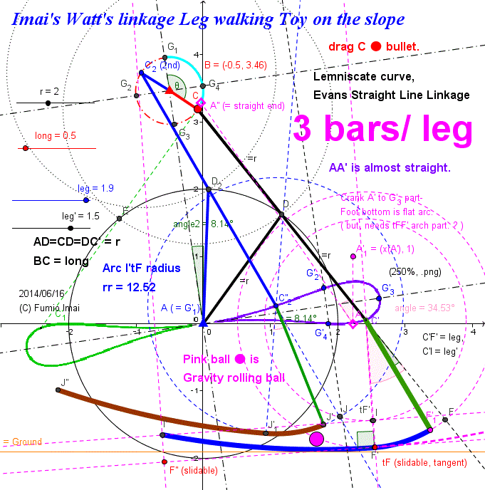
- Centipede_Watt_toy.gif -
- Centipede_Watt_toy.gif -
-------------------------------------
Imai's Watt's linkage Vertical Leg (5 bars/ leg)
Related site is below.
cf. Optimization of Watt's Six-bar
Linkage to Generate Straight
and Parallel Leg Motion
[ Figure 10. c) or d) are the same figure to the below "Tchebycheff's Engineers' Table" (up/ down is reverse). i.e. The above paper has no originality at all. but, useful. ---- I think so. ]
cf.
【Tchebycheff's Engineers' Table】 Another bit of excess - but a valid, real-life application.
http://www.mfdabbs.pwp.blueyonder.co.uk/Maths_Pages/SketchPad_Files/Mechanical_Linkages/Mechanical_Linkages.html
Below figure's Copyright is in above site all. © Mark's Maths and Excel Homepage
Here is the Anchor name = "Chebyshev_parallel_table".

My comment:
This is a table moving linkage apparatus with keeping almost exactly parallel to the floor.
(non-pantagraph parallel moving technique.)
----- proof -----
Naming of node:
( D m F) G
M
A B
(M, m is middle point)
[ where, AB = 4, height = 4 (= distance from AB to mG), AF = 5, BM = 2.5, MD = 2.5, MG = 2.5, Dm = 1, mG = 2 ]
I will prove AB // mG and AF // MG.
length condidition: mG = 0.5 AB, MG = 0.5 BD, AF = BD
and M, m is middle point.
Vector sum; AB+BD+DF+FA = 0 --- ①,
(Here, under bar mark is Vector mark.)
if so,
0.5AB+0.5BD+0.5DF+0.5FA = 0 --- ②,
0.5 AB = mG, 0.5BD = MD, 0.5DF = Dm, 0.5FA=GM
mG, GM is size is OK, but direction is not sure yet.
Next, check
△MDm. ----- △MDm ≡ 0.5 △BDF
and all direction is the same.
So, Mm = 0.5 BF
So, △MGm ≡ 0.5 △FBA
i.e. mG // AB, MG // AF are true/ proved.
So from ② is equevalent to
mG+MD+Dm+GM = mG+GM+MD+Dm = 0 --- ③
(proof end/ Q.E.D)
(The heght is almost constant is a different property. ----→ Chebyshev Linkage.)
Tip: Also, This figure indicates that Chebyshev Linkage is equivalent to Hoekens Linkage. i.e. These draw the same curve.
Tip2: If this table is set on the slope, what will happen?
Upper part will Automatically move/ slide to downward. ---- this property can be applied to the passive walking biped.
c. Watt's linkage and Chebyshev linkage are in the same family.
i.e. (Crank bar) + (2r + r , 90° generate coupler bars) sum 3 bars system
c. Recursive propety exists.
c. Below figure trick (Vector sum = zero, trick) is near the generalized Hart's A-frame trick a bit.
cf. "True straight-line linkages having a rectilinear translating bar" (.PDF) by © E. A. Dijksman (1994)
cf. Kempe's (Focal) Linkaget Generalized, particularly in
connection with Hart's second straight-line mechanism (.pdf) (© E. A. Dijksman , 1974)
c. Below vertical leg is 120° crank angle cycle, so, tri-pedal is needed.
tri-pedal is bad/ not clever.
Compromising method is adding long toe (long arc toe described in previous section). By this, 180° crank angle cycle can realize. ---- i.e. vertical leg + long arc toe (OR mode/ both function mode) ---- this is enduring to GUINNESS Book challenge. (?)
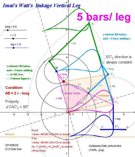
- Centipede_Watt_vertical.gif -
Please use as tri-pedal element/ component.
----- Applying to Chebyshev Linkage (bi-pedal) vertical leg version is the same 5 bars/ leg, of course. (∵ in same family). So, I recommend Chebyshev.
nodes A'1 and C'1 are under control/ fixed, So, node E is dependent/ automatically uniquely fixed.
(∵ In creating a triangle, if base edge end 2 nodes position and between of those nodes 2 edge length are given, such triangle figure is uniquely fixed/ decided. )
Another easy proof:
CC'1 and A'1A are same length and X crossed at middle point, so ACA'1C'1 is rectangle, all corner angle is 90°, then AC // C'1A'1, further △ABC and △C'1EA'1 have same length 3 edges, so △ABC ≡ △C'1EA'1, then AB // C'1E.
(i.e. 2r, r bars are an implicit parallel mechanism. so, number of bars can be decrease.)
- Centipede_Watt_vertical.gif -
----------------------------------
Here is the Anchor name = "Centipede_Watt_Leg_180deg".
Imai's Watt's linkage Vertical Leg (180° cycle)
Subtitle: Competitor method against Chebyshev Linkage
This is a method for Watt's linkage Crank angle 120° cycle extending 180° or more.
(and, Leg stroke rotates as the same crank rotation direction. --- I think this is important.)
i.e.
(a): Imai's Watt's Linkage Leg is mapping crank to X-axis bottom stroke.
but, bottom part crank angle < about 120°.
(under condition; crank center B, r/ 2r bar center A, AB = 2r -crank radius [ perhaps this restriction is big/ influenced. ])
(b): (a) environment has half stroke ( corresponding to crank 180° span) can be simulated by large radius rotating circle.
[ This large radius circle is corresponding to rr in previous Fig. - Centipede_Watt_toy.gif -. ]
(somewhat incredible matter. because (a) half stroke curve has flat bottom and acute standing curve, this can be mapping by all flat line. but, this is in real world. )
How to find such large radius circle? Answer is below.
By this we can make a great environment from ordinary environment of (a).
above-the-crank type 3 bars/ leg flat bottom crescent .
This can be shifted under-the-crank type by Chebyshev trick by only +2 bars adding. and vertical leg can get, too.
[ ADCINM crimzon color frame is 5 bars Leg apparatus. Also, ADCIKJA (including yellow-green color) is variant frame. ]
(Please review by DEMO. try to changing parameter value.)
c. This method is related to Hart's A-frame Leg and Chebyshev linkage Leg. both.
It seems as if hybrid case.
Theoretical bar length:
Theoretically below estimation is true.
Below Fig. describing at crank 180° position situation, Node I (Please tuning --- Slidable) position is decided by tuning.
but, estimation value is given as below.
Crank angle 0° corresponding position on trace is W (= crank angle 0°)
△WCI ∽ △ACD [isosceles triangle] , ( i.e. start-end crank angle 180° span triangle mapping, WI // AD. this approximation is rough but considerable good. )
WC: CI = AC : CD --- (IC + 2long) : IC = (2r - 2long) : r ---- so, IC = 2long*r / (r - 2long) [very simple]
( r = 2long case is infinite, but in real world, no problem. please try, and tuning.
--- As a matter of fact, long < 0.5r and Try N * IC ( N is Integer [N = 1, 2, 3, ...]), please.
Someone, please give me more precise formula.)
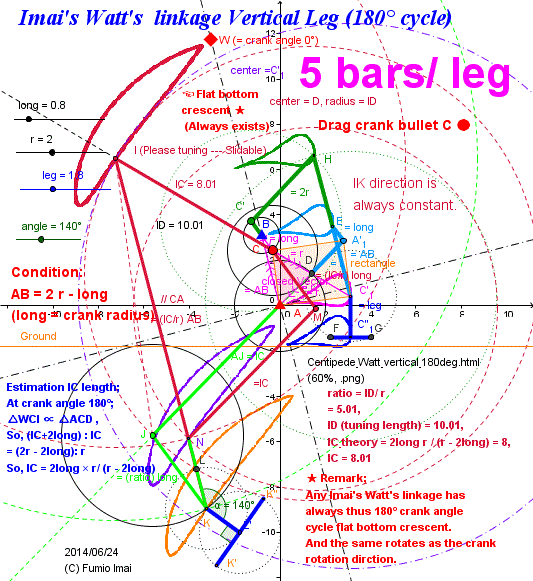
- Centipede_Watt_vertical_180deg.gif -
)
Please extend the rectangle diagonal line bar.
( toward upper left direction )
△CBA and △IKJ relation is in complement relation.
In general △ABC and base-edge AB and left edge b (= opposite to B), right edge a (= opposite to A), ------- bABa is complement to aABb triangle. [exchange a, b --- such trick]
This trick is also used in Hart's A-frame.
- Centipede_Watt_vertical_180deg.gif -
----------------------------------
Imai's Watt's linkage Leg (180° cycle) Judge
In general, Imai's Watt's linkage Leg always has its 180° type flat crescent, especially r > 2* crank radius case.
[ r = 2 crank radius, seems a border line criteria, 凹凸 switching border. Typical flat bottom crescent is r=2, u=0.9/0.8/0.7 etc. case. Now, the rotation direction of the crank and the leg stroke are the same direction. This is ordinary/ natural event. we can say that, Chebyshev linkage reverse rotation is unnatural event, now. ]
I introduce the best-fit bar length estimation tool.
Please set the input r, u [u is coming from u of unit radius]. And, find best fit XC output by yourself tuning.
(Automatic XC from r, u. formula doesn't exist yet. ----- Someone, please make it. ※)
below tool, is checking 4 points on input crank circle curve, mapping to output crescent flat bottom line.
Tip: Epsilon parameter ε is a adjustment parameter by my experiment. [ Now 0.01 is specified. but 0.005 is OK. 0.001 is BAD.]
round off the horny corners.
( --- this is corresponding to the C' trace turning angle at point A is very acute/ sharp (= zero, tangent), to reduce this sharpness. --- to shift the node A position to right bit. )
cf. Sans-serif. (wikipedia)
※ I found by chance,
(1) Before section formula is : XC1 = 2ur / (r - 2u)
(2) Long ago, I proposed formula: XC2 = (1/u)(sqrt(u^+r^)-u)(sqrt(u^+r^)+r)
(cf. Slider Curve-mapping Length law in this site. [spawns new tab])
By my experiment, both estimation result is 5030% true and 5070% false, case by case respectively.
But by my observation, mean of both, i.e. XC3 = 0.5 (XC1 + XC2) is almost 100% true.
Why? --- I don't know. --- but, very useful. ( I am a Pragmatist. (?))
[ Remark: XC2 estimation value is very precise value in FH interval. completely fit. but, this value is broken for HW interval coordination. For Compromise, this value is decreased. ]
Tip: r=4.8, u=1.6 ---- this sample is great. 4 points are colinear completely. 4.8 = 1.6 ☓ 3 --- is related?
((r=3, u=1) (6,2), (9,3), (2.1, 0.7) --- all cases, almost exact straight line, too. )
I can declare that
Imai's Watt's linkage Leg,
In ratio r:u = 3:1 case [and XC = (10/3) r or π r (π = pi=3.14..) ],
bottom is completely flat.
[ in this case, even ε = 0 is OK. but ε > 0 case is better (but, large ε is worse. ε ≒ 0 is needed.). I recommend ε > 0 applying. 3:1 case result is prominent than other case. ]
i.e. AD, DC hinge length r = 3, BC crank radius u = 1, AB = 5 (= 2r-u), CX = 10 (i.e. DX=13) [, and stride is about CX 10. ],
crank angle at K case, △ABM is just 5-4-3 triangle [ ,where M is tangent point]. and corresponding to this, △W'BK' is about 10-8-6 triangle.
(Like as Chebyshev Linkage, this Watt's Linkage, right-triangle 345 is related.)
(Please play DEMO. Perhaps, new discovery happens.)
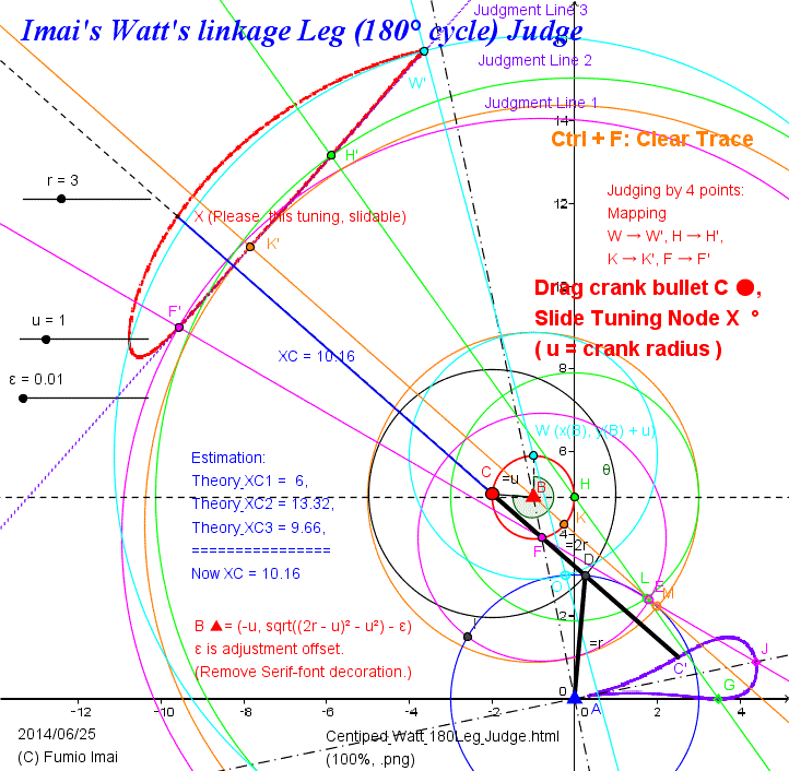
- Centipede_Watt_180Leg_Judge.gif -
By left figure case, I show how precise this exact line is.
length of F'W' = 8.95,
and define the line through F' and W', and define the intersection of line F'W' and CX line as R.
the length segment XR (= gap) is ,
from F' to H', 0 to 0.007 ,
from H' to W' , 0 to 0.047.
i.e. error rate = 0.047/8.95 = 0.005251 = 0.5251%
---- this indicates very precise / almost no error.
Chebyshev Linkage bottom line error rate was 0.25% order.
0.5% is sufficient to use in real life work.
c. Adjustment ε = 0.02 case; from F' to H': 0 to 0.013, from H' to W': 0 to 0.015, So, 0.015/8.95 = 0.001676 = 0.167% --- better than Chebyshev Linkage.
- Centipede_Watt_180Leg_Judge.gif -
----------------------------
Imai's Watt's Linkage curve
Watt's linkage (wikipedia) has 3 bars linkage, length a, b, a , and the trace of middle point M of bar b, is.
Imai's Watt's Linkage curve is variant of Watt's Linkage, 3 bars a, b, a , this is the same, middle bar b, extend the both end node by crank radius length.
ex. In below Fig. (pink 3 bars H'H'''A'A is Watt's Linkage), bar b is H'''A' → (extend both to outside) X2H'''A'X (here, X2 and A'X length are crank radius length)
node X2, X draws the closed loop, bottom is almost flat.
large radius AA' circle, small radius A'X circle, and the center of small circle moves on the large circle, and is self-spinning.
[ i.e. This is orbit of planet system. large radius is Orbital revolution, small radius is Earth's rotation. and it's related the Cycloid on 凹 curve road. i.e. especially, Hypocycloid. small-radius/ large-radius = r/R = 1/2 case is straight line (= diameter),,, --- this is in same concept.
large R length, small r length, R rotate velocity, r rotate velocity, these 4 parameters combination problem.]
large radius 凹 surface, +, 凸 curve by small radius circle (= like a Hypocycloid 凸 curve) ----- makes straight line curve. considerable good straight line. We are happy.
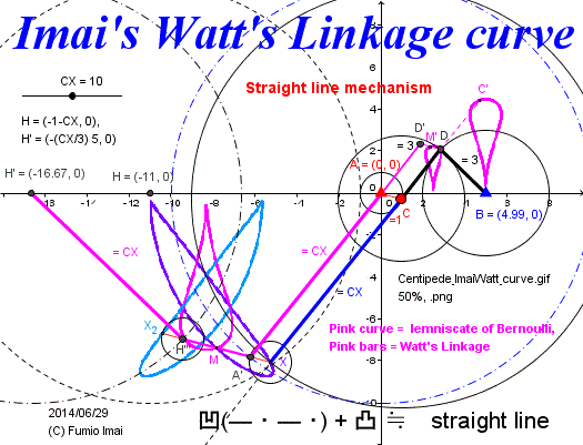
- Centipede_ImaiWatt_curve.gif -
condition;
AC = u =1, AB = 4.99, CD = DB = r = 3, CX = about 10
(key: AB = 2r - u = 5. and r/u = 3.)
AA'MH'''H' is similar to AD'M'DB.
extend ratio is, r = 3 mapping to CX, so, ratio = (CX/3).
- Centipede_ImaiWatt_curve.gif -
-------------------------
Here is the Anchor name = "Centipede_Watt_slope_toy".
Imai's Watt's linkage vertical Leg walking Toy on the slope
Please make this concept toy. Long stride non-stop walking linkage.
By the heavy rolling-balls, shifts its weight back and forth, predictively, for the inertia control.
[ At least, steep slope and short rr (= crank radius) case, the rolling ball trick doesn't need. ]
(i.e. the center of the gravity of the apparatus body is in right hand area of suppoting pivot point. both phase 1 and phase 2 cases. So, rectangle automatically expands and shrinks. --- = automatically walks.)
[ and, In below Fig., suppose the ball ● and ● were very heavy, if so, the lifting leg 100% goes ahead, so this logic is true. ]
( This phenomenon is not queer at all, as if the ball rotates on the slope automatically, or, the water wheel rotates by water stream. )
Iteration motion of expanding/ shrinking the X shaped rectangle Pantagraph (like a pair of scissors).
( Like a Geometer moth walk [see this picture. Not Marilyn Monroe - Walking (YouTube)] )
Keeping vertical standing position. And, 6 bars/ system, very compact system, without departing from the straight course.
Please challenge by this, GUINNESS Book records, the non-stop walking for one year. (Not exaggeration at all.)
cf. MEAM 248: Passive Dynamic Walker (YouTube) --- usual concept.
cf. 2 Legged Robot PLANETARY GEAR System 11102 (Posted on Jun 14, 2013, © ROBOTS ROBOTICS.) --- somewhat akin to.
c. Another condition is pending now. Under consideration. --- Found.
How to manage the heavy ballancing balls, is not difficult. there is a law/ rule.
Law: The horizontal distance between the ball and another leg is constant (or more).
( This is similar to the action of swing one's arms in walking. (?) )
[ connect the ball and another leg by stick (no rolling ?), or , pushing/ pulling the ball from the side by stick, or, magnetic repulsion force (weight slide method), or, switch the weight position by any method (possible?), or, get its Envelope curve of the ball rolling, etc.
---- but, within the same (relative) system pushing each other is in vain. needs the power/ trigger/ influence from out of (absolute) system. So, the method which searches for (absolute) more lower place is the last true method. (perhaps)
---- but, stick pushing method is easy to implementation. So, we should use this (??). ]
--- Please see the DEMO (15-b) ----- but, the simplest implementation is (15) original method.
My Request:
I don't get the best solution by this apparatus, yet. The management of center of gravity is difficult (?). but, there must be existed a solution. Please tell me its result, if you could solve it.
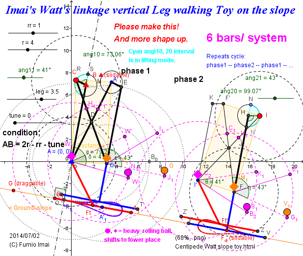
- Centipede_Watt_slope_toy.gif -
phase 1: left leg on the ground, and right leg is lifting and leaping over the left leg.
phase 2: same as right leg.
foot trace shape is upper half part of the lemniscate shape.
Key point is, whether Crank C can rotate or not.
---- that's all problem/ matter.
---- I'm afraid that stopping the crank from the first and remains in its status for ever.
Key is the design of phase 2 action.
phase 1 is no problem. Because center of gravity is already in the right hand area of the pivot point A (0,0) (= triangle corner).
In phase 2, the pivot point is F (in phase 1 C'), we must turnover/ tumble FF' bar clockwise by the kinetic moment power.
Pink color segment is horizontal angle line upper and lower limit. i.e. crank angle 0° (= phase start point) and 180° (= phase end point)....,
the meaning in detail can be understand by DEMO. Please see/ play DEMO.
In Phase 2 case, crank I rotates upward direction, so, to manage causing this action is difficult a bit. ---- balancing ball rolling (= changing the center of gravity position) is needed to manage this.
- Centipede_Watt_slope_toy.gif -
-------------------------
Simple variant
Imai's Watt's linkage vertical Leg walking Toy on the slope
(with horizontalg balancing bar)
Alias; Passive walking biped toy (long stride)
Comparison Before fig. and below fig.:
Before fig. thinking is very honest. but, tuning angles are dependent to the slope angle, it's not generalized.
On the other hand, below has independent angles, but it's not intuition.
For example: in below, suppose, I is just on N', if Add E1 more weight, what will happen?
Does triangle rotate to the right? ------ I can't predict the future by my intuition.
but, the center of gravity is in right hand area of tumble criteria line, so it will tumble.
Which is true? Before or Below? ------ Both (?)
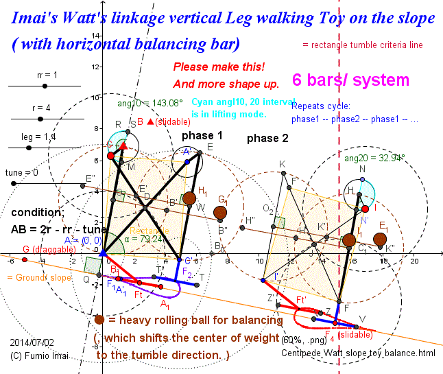
- Centipede_Watt_slope_toy_balance.gif -
Adding brown horizontal balancing bar to the middle of vertical bars.
(--- The more higher position, the more effective.)
By this, in phase 2, Total center of gravity is in the right-hand area of the rectangle tumble criteria line, so, FF' line rotates automatically to the right (i.e. the tumble can be realized).
------ this brings about happy end.
This is a symmetric solution.
Tip: This is a dynamic balancing.
So, It can be applied to right-down/ left-down mixed slope.
i.e. backward walking (switch back) is OK.
- Centipede_Watt_slope_toy_balance.gif -
----------------------
Variant: Above is equivalent to the next.
Imai's Watt's linkage vertical Leg walking Toy on the slope
( with Pendulum )
Alias; Passive walking biped toy with Carrot and stick (long stride)
I wonder if this works really? --- Please check it out !!!
( In theory, my logic is true. ---- Evident.
【 In rigid body dynamics, the condition to tumble or not is dependent to the position of its center of gravity, not related to the inner structure. inner structure can be regarded as black box. 】 )
cf. Lever/ Law of the lever (wikipedia)
cf. overturning moment (in Japanese page,,, Letter maybe broken, but Fig. is international.)
--- See, last figure. left moment = 5t × 3m = 15 [tm], right A moment = 3t × 4m = 12 [tm], right B moment = 3t × 6m = 18 [tm] , ---- So, case B, the crane turnover will happen (∵ 18 > 15).
Tip: This implementation has many variations. If biasing the center of gravity , any method is OK.
----- Center of gravity of this 6 bars original apparatus is in about almost K position, So, adding stick and carrot causes to shift its center of gravity to the right direction. --- this is valid. It can be easily understood.
( i.e. this apparatus, phase 1 and 2 both are always in overturning mode. it has good successful structure. )
Tip2: Imai's Hart's A-frame 5.5 Leg for Non-stop record (Vertical Leg) is also passive walking biped itself. I think so.
(but, the Watt vertical is simpler than the A-frame vertical. why. because, adding the weight is corresponding to one specific leg, so, after the pivot leg switched , the weight effect doesn't work. this property is very useful. (?) ---- i.e. Even if adding very heavy weight were done, it doesn't effect/ influence another leg. it's Like a orthogonal axis property.
To realize this overturning moment trick, the A-frame needs adding to the vertical bar the longer stick and carrot bar. but the A-frame case, its top position (= crank center = waist position (?)) trace draws exactly the straight line parallel to the slope.)
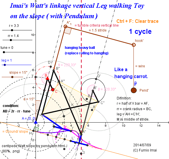
- Centipede_Watt_slope_toy_pendulum.gif -
right down slope case sample.
Carrot and stick (wikipedia)
cf. YouTube: Carrot Stick Riding
As a matter of fact, wire length ZERO is OK.
- Centipede_Watt_slope_toy_pendulum.gif -
----------------------------
Imai's Chebyshev linkage vertical Leg walking Toy on the slope
( with Pendulum )
Application: I provide this for studying.
Please brush up more.
Chebyshev case, perhaps more improve/ more tuning is needed. I don't satisfy now.
impression/ feeling: Chebyshev bottom and roof shape is near the flat, so, it works by lower energy.
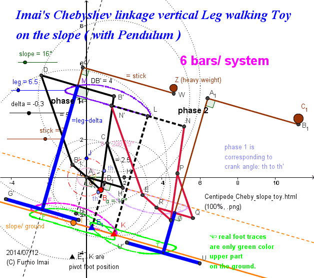
- Centipede_Cheby_slope_toy.gif -
phase 1 is pivot vertical leg is on E1 ▲.
crank angle interval is from th' to th (anti-clockwise direction). foot trace is arch.
phase 2 is on K ▲.
crank angle interval is from th' to th (large angle). foot trace is \―――――/ shape.
It looks like no need adding weight.
I don't know.
I can't explain by intuition.
length: AB = 1 (crank radius),AH' = 2, H'C = 2.5, BC = 2.5, CB' = 2.5, DB' = 4, B'1D = 5, M (mid of DB' ) trace bottom from A = 4.
Someone, please show the true answer.
------------
right down direction force by gravity is fit.
but in phase 2, Can you explain the first up "\" action ?
this action is caused by N'E (N' is fixed, E moves to the right) rotates anti-clock. and this is caused by NO (N is fixed, O moves to the right) ----- these are induced by heavy C1 ●. ------ this is somewhat odd (?).
I can't understand by my intuition.
Something another trick/ concept is needed, perhaps.
c. ---- phase 2 , real pivot of lever is N' or N, and hanging lever. So. additional weight must be in left hand area. so, C1 right hand picture is mistaken.
- Centipede_Cheby_slope_toy.gif -
------------------
the same. revese type.
Imai's Chebyshev Biped Toy
I am satisfied, now.
c. new variant: It looks Ok another simpler method (?). i.e. Not adding L letter weight to D or O', lengthen PN to PNP' and add P' position the weight, this causes PN rotates clockwise power (here, N is fixed point), so induces the crank radius counterclockwise easy rotation. --- please try.
c. the L letter bar weight logic is mistaken. feeling is OK, but, the shift of center of gravity doesn't happen. its gravity center is on vertical line of just under the hanging D or O'. This mobile sculpture is (only) the same as one weight. --- But, feeling is important.
c. If one motor were supported, applying to m (or N') point, the biped can be made easily.
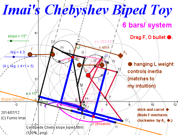
- Centipede_Cheby_slope_biped.gif -
AB (= 4) is leg foot itself.
Simpler than before.
in phase 1, By Pivot B, bar FB overturns clockwize by the weight A1 ◆.
in phase 2, swinging motion of the bar. but at the beginning, trigger force is needed to lift the foot.
( my feeling: this swing motion is corresponding to the cycloid motion ( under 3 distance), π r = 3.14 (180°) is to 4.0 (=AB), i.e. crank rotation is to circle rotation on the flat road. i.e. Chebyshev crank rotation is 1 to 1 mapping to circle rolling on the road.)
the L letter bar weight ● on the crank.
(almost horizontal.)
Keeping the heavy crank in the left hand area of the circle.
( induces counterclockwise crank rotation. )
- Centipede_Cheby_slope_biped.gif -
------------------
Roberval balance
I produced next apparatus. Is this a perpetual rotation machine, isn't it?
( and Please apply this crank to the passive walking biped. )
feeling:
Crank A (A is an axis/ axle of this crank), diameter BB', both end B, B', set the heavy balls D, D' to the horizontal left hand of B, B' (where, distance DB is constant.).
[ BC, CC', C'B' additional bars are making horizontal bar mechanism. A' is mid of CC', and is the fixed point on Y-axis. ]
What will happen?
( Rigid body of this apparatus (= crank bar system). The supporting pivot point is A (0, 0). but, center of gravity is M (= different constant point from A) (-d, 0). i.e. A ≠ M. ----→ usually, it automatically rotates by unbalancing.)
c. I tried many other structure, but all were failed. but below is stable and successful (?).
other cases, pedal downward is Ok, but upward supporting force was insufficient.
M is exactly fixed point. if d = 0 --- then M = A, this case is typical case, if no-friction, crank rotates forever by initial force with hand (but, automatical rotation doesn't happen). the Same analogy exists in d > 0 case; if no-friction, the rotation doesn't stop. and M is in the left, so automatical counterclockwise rotation will generate.
--- or Otherwise, if friction is big, make d big, perhaps can overcome the friction. (?)
(M position doesn't change. i.e. pedal downward force = other pedal upward force feedback is done at any time, this simplicity is good.)
Tip: About Roberval balance:
Gilles de Roberval (French mathematician, was born at Roberval, Oise, near Beauvais, France. His name was originally Gilles Personne or Gilles Personier, that of Roberval, by which he is known, being taken from the place of his birth.) Roberval is French province name.
In below figure, gravity is up to down = vertical direction.
Suppose D and D' weight hanging to B and B', by wire, if AB = AB' and D weight = D' weight, then this is balancing. long wire/ short wire is indifferent.
We think, this fact is of course/ self-evident matter.
If so, suppose, gravity, right to left direction (= horizontal gravity). D and D' is hanging from B,B'. BD // B'D', and length DB is indifferent.
I think so. this paradigm shift is occured/ simulated by Roberval balance parallel bars trick.
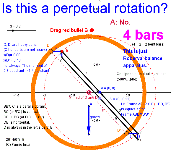
- Centipede_perpetual_crank.giff -
Suppose, except D,D' all other weight can be neglected.
Node D, D', distance form Y-axis,
when x(B) ≤ 0;
2d ≥ |x(D)|-|x(D')| ≥ 0.
when x(B) > 0;
2d ≥ |x(D')|-|x(D)| ≥ 0.
So,
Always, counterclockwise rotation power is given.
(and, center of gravity of this rigid body is M ◇ (-d, 0). this is fixed point.)
Is there logic miss?
→ Yes, it's Logic miss
--- cf. Roberval balance (wikipedia),,, or cf. (2), (3) YouTube,
if So, D, D' orthogonal projection foot on radius BB' points as the new D, D' position works well?
i.e. D, D' weights slides on BB' bar. Even in this case, Roberval balance law is true?
cf. "Overbalanced Wheel (in wikipedia)" -- In this wikipedia sample, gravity average center is just under the axis (?).
but, in my left fig. case is not under, in the left. torque is not balanced.
and, the number of my metal balls is just 2.
To put it plainly, in the left hand of circle , radius is long a bit, in right hand, radius short a bit.
- Centipede_perpetual_crank.gif -
-------------------
variant of above.
Challenge again.
Imai's Perpetual Motion ( with proof )
Very simple structure.
cf. An Analysis of a Perpetual Motion Machine (WIRED.com © 2014 Conde Nast. )
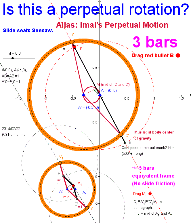
- Centipede_perpetual_crank2.gif -
A' is horizontal left side from Crank axle A.
C, C' are heavy slide weight.
if no-friction, this apparatus spins forever.
Just M is on A point is a critical point. vertical diameter becomes balancing (= stopping peak point). but, usually is passed through by inertia force.
Other x(M) < 0 point is stable counterclockwise power is caused.
Exercise: Please prove next.
(1) C trace is circle. ----- easy.
(2) M trace is circle. ----- not easy (?) [∵ △A'MA is right triangle.]
( (2) is a good problem. )
------------------------
lower picture is an equivalent frame.
pantagraph is middle point generator linkage.
I'm afraid " this is miss logic, too. the same illusion" (?)
c. This structure which is including pantagraph is similar to the Peaucellier Linkage a bit. --- why?
c. Near the below. ---- but, I'm in frustration. Please show me the trace of center of gravity of the apparatus body.
cf. Spring Engine. Пружинный двигатель (YouTube)
cf. overbalanced cross
c. My simple impression: upper fig. is unbalancing torque (pivot = A). but, lower fig. looks like a balancing torque (pivot = M1). --- which is true?
(i.e. traces of upper/ lower cases are all the same. lower is pivot is M1 and weights C1, C'1 are balancing. but the position restriction exists, (1) M is on the circle mid. (2) C1 A'1 distance is constant.
lower is balancing, so, automatic counterclockwise rotation torque is not existing. ----- this is against the upper fig. thinking property. --- paradox? ,,, which is true?
otherwise, both is true? ---- from M1 view, balancing. but, from view A1, unbalancing. ---- so totally, from the 3rd person view, unbalancing.
--- Someone, Please judge this.)
c. in below fig., point A1 is not explicit. Suppose A'1A1 segment bar, and Please Put/ support A1 on your finger top.
the Mobile sculpture will overturn to the left, perhaps.
• Put on mid on your finger top, the mobile ----- what happens?
• Put on M1 on your finger top, the mobile is balancing.
Worst case: upper case (3 bars) is balancing. ---- I can't imagine. --- false, Absolutely.
- Centipede_perpetual_crank2.gif -
※ (About Japanese culture:) Japanese elementary school kid all know this value. Q. WHY? --- A. It's learn by heart. There is a famous pun.
another samples; √3 =1.7320508, √5 =2.23620679 ,not difficult things at all, for us.
(nuance of meaning; root2= one night by one night, grows good looking [about cherry blossoms (?)], root3= like other people, please buy me anything. root5= at the foot of Mt. Fuji, parrot sing.)
( Related my service;
Let's have a white Christmas in HAWAII, Japan Air Lines
. --- 3.1415926535 -- This π (pi) learn by heart method is my invention. Christmas = 9 characters. [ My sample of 10 digits after decimal point. ]
(No <ruby> form: Let's have a white Christmas in HAWAII, Japan Air Lines. 3.1415926535 )
---- cf. Pi Day [March 14 (or 3/14)], Albert Einstein's birthday )
- Centipede_Cheby_45_slide_symmetry.gif -
Imai's linkage (tri-pedal)
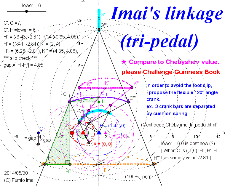
- Centipede_Cheby_imai_tri_pedal.gif -
Left figure indicates the mapping relation of between crank angle and trace position.
Now condition is just, -180°, -180+120°, -180-120° crank angle input.
output H'', H', H''' are on the same y position value.
but Chebyshev out put K'', K', K''' are different y value (precisely). [4.00 ≠ 4.06]
arm3 = 7, arm4 = 6 estimation is granted/ supported by theoretical analysis easily. Left green triangle relations derives the Set of its value.
- Centipede_Cheby_imai_tri_pedal.gif -
----------------------
Here is the Anchor name = "Centipede_Cheby_imai_arm34".
arm4 Theoretical Estimation (arm3, arm4 rule);
By my experience arm3=7, arm4=6 pair was good result. now I I've already gotten the information of Crescent curve, so, arm4 mathematical estimation is easy.
Assumption; I suppose that almost straight is defined as -180° crank and -60° crank has the same mapping bottom line y-value.
(i.e. In above Fig. we find, always y(H'') = y(H') satisfying condition. Very rough approximation, but in good environment.)
Under above assumption, I try to get the solution.
In above Fig.
C (-1, 0) [-180°] --- C'1≡ (√2, CC) = ( √2, sqrt(13-2√2 ) ) = (1.414213562, 3.18929034)
C' (0.5, -0.5√3) [-60°] --- C''1≡ (X, Y) = ( √2-sqrt((3/4)[-1+16/(3-√2)]), (√2-0.5)*(X-√2)/(-0.5√3) ) = (-1.196767719, 2.756263832)
suppose arm3 = G'''G''1, arm4 = G''1H''
[ H'' ∝ ((√2-X)+((√2-X)/arm3)*(arm4),CC-arm4) ]
Then, next equation is true.
arm4^ = [arm4-(CC-Y)]^ + [((√2-X)/arm3) * (arm4)]^ ------ eq.(1) [ Please consider its meaning.]
[ i.e. in △C''1H''H; C''1H'' = arm4, C''1H = arm4-(CC-Y), H''H = ((√2-X)/arm3) * (arm4) ]
simplifying; suppose z=arm4, aa= ((√2-X)/arm3), then
z^=(z-(CC-Y))^ + aa^z^,
z^=z^-2(CC-Y)z +(CC-Y)^ + aa^z^ --- so, aa^z^-2(CC-Y)z +(CC-Y)^=0
So, z^ -2(CC-Y)/aa^ z +(CC-Y)^/aa^= (z-(CC-Y)/aa^)^ -(CC-Y)^/aa^^ + (CC-Y)^/aa^=0
So, z= (CC-Y)/aa^ +- sqrt([(CC-Y)^/aa^^][1-aa^]) = (CC-Y)/aa^[1+-sqrt(1-aa^)] --- eq.(2)
At last choose (+) answer; z= (CC-Y)[1+sqrt(1-aa^)] / aa^ --- eq.(3)
i.e. arm4 = (CC-Y)[1+sqrt(1-((√2-X)/arm3)^)] / ((√2-X)/arm3)^ --- eq.(3')
this is last answer. [insert CC= 3.189..., X= -1.196..., Y= 2.756...]
Set of (arm3, arm4) sample are: (7, 6.00029117), (6, 4.345536359), (8, 7.907885913), (9, 10.06888523) (15, 28.36558953), (20, 50.59814408), ....
So, (7, 6) estimation is valid. (Proof End.)
Check it out by below DEMO "(13-h) Imai's linkage ( arm3, arm4 rule )"
c. (15,28) case I checked. --- this is valid. but stride is not so large, -6.5 to 9.3 i.e. stride = 15.8 [stride multiplying factor is (arm3+ arm4)/arm3 = 1 + (arm4/arm3) = 1+28/15=2.87 multiply,,, (7,6) case was 1+6/7=1.86 multiply
Exercise: Different criteria, -180°, -90°, +90° crank angle has the same mapping leg height.
Please solve this condition. what is arm3, arm4 rule?
(answer:) -90°; (x,y) = (0,-1) --- (X,Y) = ( √2-√(13/3), √(26/3) ), other value is the same. eq.(3) is the same, too.
result set samples (arm3, arm4) = (7, 5.423613634), (6, 3.950300381
), (8, 7.123018678), (9, 9.048693715), (15, 25.35745464), (20, 45.17606734)
total estimate: is worse than 120° criteria. is not a local minimum point. left/ right end area is below than center. --- it looks bad.(?)
.
Tip: If the horizontal line H''HH'H''' is the exact straight line, the middle of G'''H''(= length arm3 + arm4) traces the circle with center H' (= center of bottom line). but, in real system H''H''' line is the curved line, so I think the C''1C'1C''' curve is approximated by x=√2 symmetric crossed circle's upper parts. i.e. overlayed 〇 + 〇 shape. ︵︵ shape like a 凸凸 (= 2 humps) shape. Precisely, left ︵ is inclined -α°, right︵ is inclined +α° , and middle of ︵︵ is flat.
so, y(H'') = y(H'), but y value of between H''' and H' is ≧ y(H'). Precisely, H''H'H''' is near ︶︵︶︵︶ shape.
-----------------------------
Equivalent frame
In Chebyshev linkage (wikipedia), ratio of bars are defined by
L1 : L2 : L3 = 2 : 2.5 : 1 = 4 : 5 : 2
Same relation are there, as below.
L1 : L2 : L3 = √2 : 2 : 1 = 2√2 : 4 : 2
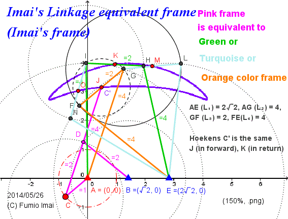
- Centipede_Imai_frame.gif -
Left frame has a similar relation as Chebyshev Linkage and Hoeken's Linkage.
4, 4, 2 (base edge = 2√2) length 3 bars frame draws the same trace of Pink crank drawing trace.
Orange is cross frame.
The most left or right corner of curve parts are drawn by Turquoise color frame (including Orange or Green eventually).
crank angle // frame upper edge
(i.e. CA // FG )
- Centipede_Imai_frame.gif -
-----------------------------
Another sample
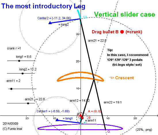
- Centipede_Cheby_0_slide_intro.gif -
Sample of the symmetry crescent by vertical slider.
This is the most typical apparatus, but stroke turning angle is 180°, so I recommend the tri-legs component/ set.
- Centipede_Cheby_0_slide_intro.gif -
----------------------------
Another sample
Imai's Linkage (bi-pedal with foot)
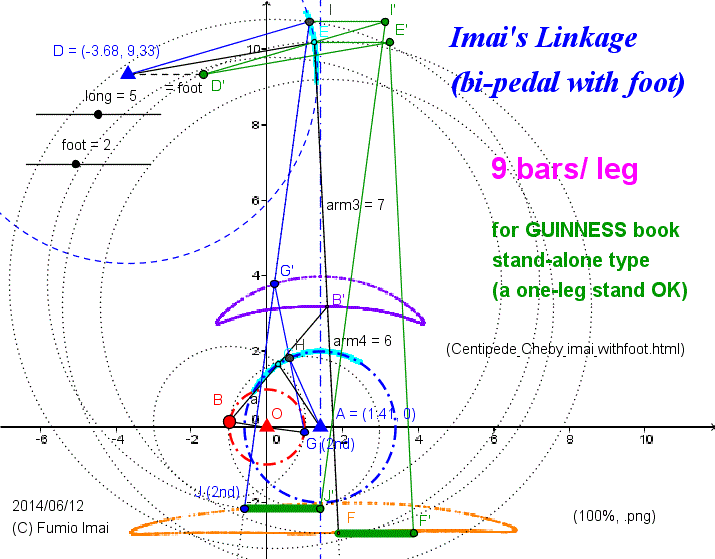
- Centipede_Cheby_imai_withfoot.gif -
Ensure verticality
( = O▲A▲ // Ground)
I think tri-pedal type is nearly equal to this.
( ∵
(1) tri-type is ensuring verticality too.
(2) 15 (3×5)bars/ system, left type is 17 (18-1)bars/ system.
(3) but, left type can have +- both side foot, and big foot.
(4) left structure is simple, and robust.
[ex. tri-type legs chassis structure/ design is much complex than bi-type, in bi-type, 2 surface (= both side) of one crank plate is enough. tri-case, one more crank plate is needed. so, bi-pedal is preferable in real implementation.]
)
c. near the 4 legs system, too.
- Centipede_Cheby_imai_withfoot.gif -
Tip: Above bi-pedal has a foot, so it can stand by one leg, and doesn't tumble [ by wide foot]. So, if set on the slope, Please check to move automatically by self-weight (= gravity) or not.
If not move, Please set more acute slope angle.
And please challenge the GUINNESS Book non-stop records.
Parallelogram EFF'E' ( or D, D') needs to be inclined and be changed to thin/ flat . If necessary we make the head node E and E' to be heavy. Hide the rolling heavy ball in it (?). --- please investigate this non-stopping mechanism !!!.
cf. The Design and Optimization of a Crank-Based Leg Mechanism (.pdf, by (C
) Amanda Ghassaei and Professors Phil Choi and Dwight Whitaker in Pomona College Department of Physics and Astronomy, @2011)
excerption; (from p47) ----- I attached the inverted Chebyshev linkage to an inverting linkage
so that the locus will be flipped over to its original position (Figure 4.2.2 B).
Although the torque on the inverted Chebyshev linkage is too great to make it a useful leg
mechanism,----
My comment; ---- too big torque to move??? ----- Please tell me, how to calculate the torque value?
Please show the each/ respective torque values, Fig. 4.2.2.A, Fig. 4.2.2.B, Fig. 5.4.4.(= your last answer), Theo Jansen Linkage, and my Imai's Linkage cases.
Here is the Anchor name = "a=b". ---- Alias: Musashikoganei 49-frame
I introduce to you the/ MY 9 bars exact straight line drawing apparatus.
(This apparatus comes from 3D 4 bars exact straight line drawing apparatus.)
Detail is below.
Generalized Hart's A-frame Online DEMO (© F.IMAI, GeoGebra Java applet)
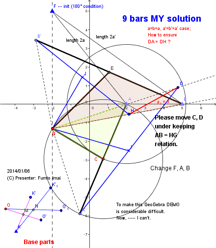
- Fig.1C_a=b -
This is educational.
Why does this work correctly? ---- Please consider.
Very simple logic, but many bars. (?)
( At least, this logic is easier than Peaucellier or
Hart's A-frame logic. )
Length recipe:
long bar length = 2a', short bar length = 2a,
Half length bar from the middle point of each bars.
Bridge bar HG length = AB
- Fig.1C_a=b -
Here is the Anchor name = "H_inversor".
What is Hart's Inversor?
This is the promotion for the variation of Hart's Inversor DEMO .
I show the usage of the external division point in Hart's Inversor.
[ I think/ believe external case is more useful than internal division ordinary case in real life. ]
---- WHY unknown this fact? , Harry Hart didn't know???
Detail is below.
Generalized Hart's A-frame Online DEMO (© F.IMAI, GeoGebra Java applet)
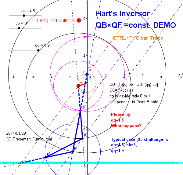
- Fig.1C_H_inversor -
Points B, Q, O are the external division point.
These are end points of bar.
5 bars apparatus.
If you want to know more, Please go to above DEMO site.
I deregulate the restriction 0 < μ < 1.
(cf. Hart's Inversor by © Alexander Bogomolny)
--- I promote μ > 1.
I will show the real usefulness of Hart's Inversor apparatus.
I think "Interoperability of ordinary internal division type Inversor is bad.".
---- i.e. It's difficult to handle.
- Fig.1C_H_inversor -
Here is the Anchor name = "H_inversor_gear".
Hart's Inversor is a 2 Ellipse GEARs Hinge
Detail is below.
Generalized Hart's A-frame Online DEMO (© F.IMAI, GeoGebra Java applet)
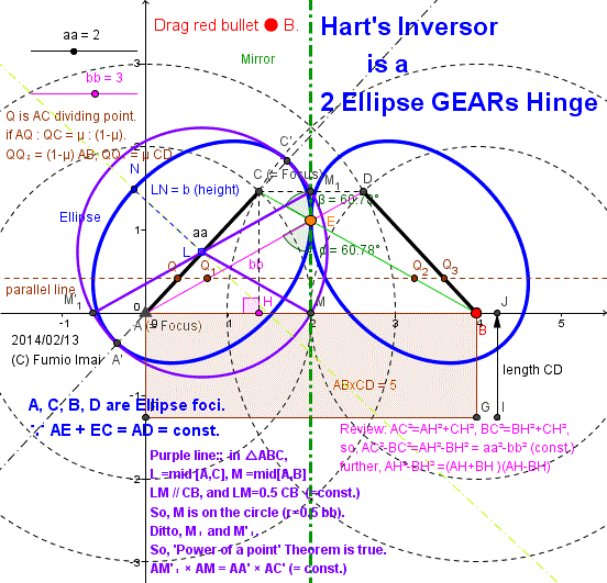
- H_inversor_gear.gif -
Hart's Inversor is the hinge
which is composed by 2 Ellipse GEARs.
i.e. Symmetry angle generator apparatus.
How to control this hinge?
Tip: Left figure shows.
The sum of 2 distances
from the Ellipse foci to the curve, is constant.
--- true.
The product of 2 perpendicular distances
from the Ellipse foci to the tangent line, is constant.
--- perhaps, true.
( sum = const. is equivalent/ reduced to product = const. )
cf. Conic sections - Focus properties © Mad Maths (Recreational mathematic collection)
~ The product of distances from focii to a tangent is constant and equal to b2 : ~
My proof: in above △ACE, suppose AC=c, CE=a, EC=b, ∠AEC=T, then, c2 = a2 +b2 -2ab cosT= (a+b)2-2ab(1+cosT)
Here, ellipse case, a+b=const., so 2ab(1+cosT)=c2-(a+b)2=const.-const.=const.
so, 2ab(1+cosT)= 2ab 2cos2(0.5T) = 4[a cos(0.5T)]×[b cos (0.5T)] = const. --- this is eq. to --- CM1×AM = const.
Tip1: distance LM1=LM=const. i.e. M1, M traces circle from center L. --- this is related to "Power of a point" theorem.
Tip2: Point E traces the ELLIPSE curve. E is "Harmonic MEAN" division point on M1M for height (CM1 and AM).
[ ● E's position distance is proportional to each end height. so, it locates near to the short height side. --- i.e. HARMONIC mean is on the side of the little guy.
In Linear perspective (= Scenography), E's position is the point which AB, CD are looked as the same size.
(ex. The Sun and the Moon appear to be roughly the same size because the Sun, although much larger.)]
Tip3: (In "Power of a point" Figure,) Peaucellier Inversor implementation is the horizontal symmetry of △LM'1M and bar LA, Other wise, Hart's Inversor is the vertical line symmetry of △LAM.
- H_inversor_gear.gif -
---- This is new-type of "product = constant." apparatus. i.e. QQ1×QQ2 = constant. (= variation of AB×CD = constant [= (2b)2].)
cf. Power of a point (wikipedia) ---- Peaucellier Inversor hint.
MY Question:
Non-slider type Ellipse drawing can be done by "Hart's Inversor (5 bars) straight line + 2 bars" or "Hart's A-frame (5 bars) straight line + 2 bars". --- Total 7 bars system.
Are there more simpler apparatus in the world? --- YES. --- It's possible by 5 BARS.
Hart's A-frame. A(0,0), B(dd,0) and x=0 ( =Y-axis) straight line. in this case, 2 bent bars from A(0,0) doubles as an Ellipse drawing apparatus.
See Fig.15 (And consider deep.)
cf. Link1. Linkage --- Last figure (No.10) is "Hart's A-frame straight + 2 bars" case.
[ In this figure, Fixed horizontal base bar is fixed on the ground, so, it omits to count the number. i.e. real needed bars are, 8-1 =7. ]
--- No. 4 case is straight line + Peaucellier Inversor. ---- Now, I'm checking this logic. I doubt this.
--- No. 6 case: This figure is not an ellipse. oval/ egg only. And blue color frame is redundancy.?? --- mistaken/ miss logic. Who made this? Made in Taiwan?
(This figure is like a Cassini oval curve which is not a ellipse curve. Please precise review.)
Link1. No.6: http://apollonius.math.nthu.edu.tw/d1/gc-02/gc1802/1030/1029-6.html ---- There exists mistaken. where?
---- I found a right original page. Link2. http://apollonius.math.nthu.edu.tw/d1/gc-02/gc1820/10_30/10_30.html
This No.5 fig. is true figure. --- i.e. above Link1. No.6 is corrupted (i.e. inner ellipse blue curve is lacked.). --- evident. ---- Who copied this page?
cf. Link3. http://sylvester.math.nthu.edu.tw/d2/app09/linkage/15.html --- this picture is mistaken. --- foolish!! Who made this? 6 bar (odd) ---- 1 bar (restriction bar) was lacked. no-review...bad system
Here is the Anchor name = "Inversor_mapping".
Inversor Mapping
2 typical case: (1) Line (2) Ellipse
( Hart's Inversor edge middle point trace is not the real Cassini Oval curve. --- i.e. CG×C'G ≠ constant.)
----- This Cassini-like figure is the same as above my Cassini Square Wheel figure. [= Chebyshev Linkage modified action]
---- This crank property is better than Chebyshev Linkage modified crank action. There's no collision problem. WHY?
Tip: Perhaps, Pink ellipse and Lime-green Cassini-like are intersected orthogonally.
cf. Samples of (2) apparatus: Linkage to Draw an Ellipse
( http://sylvester.math.nthu.edu.tw/d2/app09/linkage/7.html or
http://sylvester.math.nthu.edu.tw/d2/app09/linkage/14.html )
Detail is below.
Generalized Hart's A-frame Online DEMO (© F.IMAI, GeoGebra Java applet)
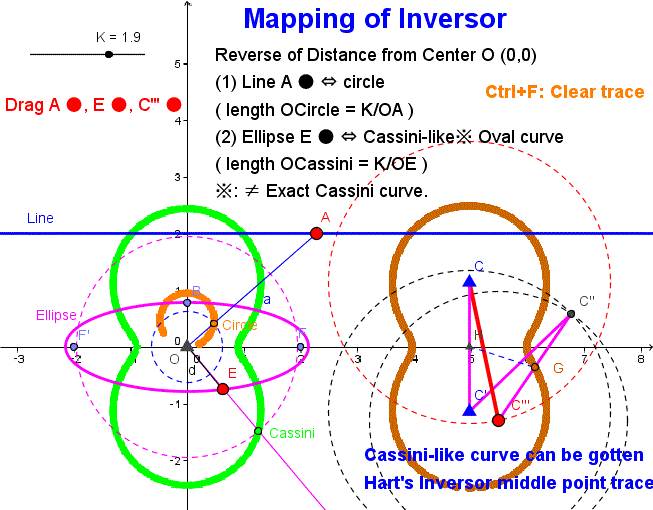
- Inversor_mapping.gif -
As a matter of fact,
Circle ⇔ circle
, then
Line ⇔ circle
eq. to
Circle (r=∞)⇔ circle
- Inversor_mapping.gif -
Here is the Anchor name = "Hart-ellipse".
5 Bars ELLIPSE drawing
This apparatus was famous (from old time). cf. Guida rettilinea di Hart (2°). --- in which, Please Click + (Plus Mark) icon to start amination. (☓ icon is "stop/ Reset".)
cf. Figure 7. in On Burmester's Focal Mechanism and Hart's Straight-line Motion (.pdf) by © Prof. Dr. W. Wunderlich 1967
But, There was not in the Image-site of Google keyword search "ellipse linkage" result. ---- It's bad※.
(From precise check, I found "Hart's exact straight-line mechanism" figure sample, but this figure has no ellipse trace shape. i.e. bad figure.)
[AD = DA --- odd. AD = CD --- true. i.e. typo.]
※: With the wisdom of hindsight, Circle is realized by 1 bar, and Straight line is done by 5-bars. if so ellipse is done by 7 bars ---- this is very odd. Don't you think so? It must be done by 5 bars.
Detail is below.
Generalized Hart's A-frame Online DEMO (© F.IMAI, GeoGebra Java applet)
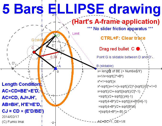
- G_A_ellipse.gif -
This is famous apparatus.
(but, less well-known. -- It's so pity.)
A(0,0), B(x(B),0) are fixed,
D bullet • moves on y-axis from (0,2) to (0,-2) piston movement.
Bar length: (here, E' = E mirror)
AC = 1, CD = 1,
---- AC*CD = BE'*DE'
BE' = 0.5 [sqrt(4 + x(B)2) + x(B)],
DE' = 1/BE' --- = 0.5 [sqrt(4 + x(B)2) - x(B)]
CJ = CD * (DE'/BE'), E'H' = DE' * (CD/AC),
JH' = AB * (DE'/AC) --- = bridge
Point G on DD'1 segment. G traces Ellipse.
if G = C --- traces circle. fat ellipse.
if G = D or D'1 --- traces line. twiggy ellipse.
(D side --- Y axis type. D'1 --- X axis type)
i.e. This converts from circle to ellipse.
circle → straight line → ellipse.
( straight line is intermediate.)
Remember:
• Always ∠ DCA = ∠DE'B. and,
• When D is on the A (i.e. ∠ DCA = ∠DE'B = 0°), all points are crushed in a line, So, H' and D are on the A (i.e. = same position).
• Initial Limit case ∠ DCA = ∠DE'B = 180°, bent bar is straight. So, length (AC + CD) and (BE' + E'D) are dependent.
(ex. in above case [= D is on (0,2) case]; (AC + CD)2 + AB2 = (BE' + E'D)2 is established.)
- G_A_ellipse.gif -
Essence of A-frame:
I summing up the Hart's A-frame trick by this typical case.
① if D traces the straight line which is orthogonal to AB line, it's needed,
"DB2-AD2 = constant (difference of 2 square distances is const.)" --- (p1.; property-1).
② in order to make the variable DB, AD edge, we adopt the bent bar.
Further, to keep property-1, we decide "AC*CD*cos(∠ DCA) = BE'*DE'*cos(∠ DE'B)" --- (p2.; property-2)
To p2. we decided, AC*CD = BE'*DE' restriction. --- (p3.)
this is necessary condition.
[i.e. notation simplify: ab cosγ = a'b' cosγ' , ab = a'b' , here γ is symbol GAMMA.]
③ We must to keep next.
∠ DCA = ∠DE'B --- (p4.)
[i.e. γ = γ' --- this is eq. to, α + β = α' + β' , here, α, β, ... are foot angles.]
what shall we do? More restriction needed!!!
Such answer exists. △ADB ∽ △H'DJ (not △JDH', oblique lines relation was exchanged. and bent bar are upside down. )
[ i.e. w Cross-Exchanging has done.
(a, b, α, β) exchange to (b', a', β', α'),
(a', b', α', β') exchange to (b, a, β, α),
and angle rotate shift of layout is "old-new (or mother-baby inheritance)": α - β', and α' - β
---- Oh my God! α - β' = α' - β (from p4.) ----- so, the same shift angle!!! ---- i.e. always ∠ADB = ∠H'DJ ]
Such clamp bridge would be introduced the bar JH' ― (AB is always constant, so JH' is constant.). --- (p5.)
(△ADB ∽ △H'DJ proportion ratio is from p3. i.e. constant. DE'/AC (= or CD/BE') , i.e. JH'/BA = DE'/AC )
Tip: Hart's A-frame is Piggyback style system. and Recursive system.
Here is the Anchor name = "Inverse_meaning".
The meaning of Inverse property
Detail is below.
Generalized Hart's A-frame Online DEMO (© F.IMAI, GeoGebra Java applet)
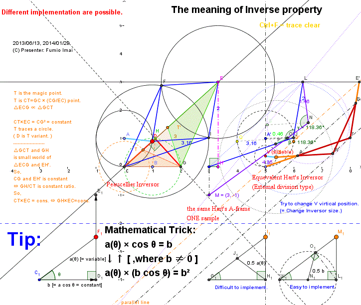
- Inverse_meaming.gif -
Peaucellier vs.
Hart's A-frame vs.
Hart's Inversor
Please check, different.
Orthogonal projection;
a cos θ = b (= constant)
is equivalent to
a [b cos θ] = b2 (= constant)
↑ This is the Inversor equation,
itself.
- Inverse_meaming.gif -
My complaint: What I really need is (length 1 [= unit, constant]) position indicating apparatus, rather than (0, m , 1/m) positions indicating apparatus.
i.e. (0, 1/m, 1, m) all points sequence is needed.
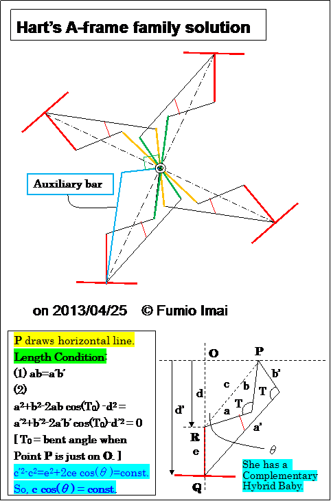
This is an application sample by Hart's A-frame family.
This A-frame is generalized※ than original usual A-frame linkage.
※:
This generalization was found by me. (?) , maybe ☆.
It depends on (1) and (2).
Remark:
- Bent bars pair (a, b) and (a', b') always have the same bent angles "T (this is changing)" each other.
- Shape is close to the real animal leg/ knee. isn't it?
☆: Already found by other person. At least below. but different point of view.
"True straight-line linkages having a rectilinear translating bar" (.PDF) by © E. A. Dijksman (1994) --- excellent material, I think so.
Detail is described below.
(If you have a curiosity, please read. cf. Fig.12 ~ Fig.17)
{ There exists the duality between "Hart's A-frame" and "Peaucellier linkage".
--- i.e. (1) ab=a'b' corresponds the inverse property.
This duality was also found by me. (?) maybe.}
This is simpler than Fig.1
There are not critical situations, so Parallel control Link doesn't need. (?)
(or Having a compact line-symmetry structure.)
Left exact straight line drawing apparatus (alias name =
Advanced A-frame) proof is the good mathematical/ geometry problem (for High school level students).
"Law of cosines" knowledge is required.
Tip: If T0=0° is specified, a=±d+b, b=b is a result [ ∵(a-b)2-d2=0 ].
a=d+b, b=b is famous(?) and versatile, but is a tip of the iceberg.
T0 provides the minimum bent angle. ∵ The minimum distance point to the line is at O. We can control this value. This is good thing.
She has a similar shape triangle baby which 2 edges are exchanged right & left, and replaced into complementary bars. --- Strong trick (or magic) !!!???
Generalized Hart's A-frame Online DEMO (© F.IMAI, GeoGebra Java applet)
- Fig.1H -
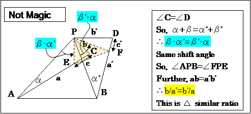 - Fig.1J -
If you have a deep insight/ intuition, can feel/ make/ solve this trick.
Here,
c = b(b'/a'), c' = b'(b/a)
[ ratio: b → c',so, c'/b=b'/a ; b' → c,so, c/b'=b/a' ]
α=∠CAP, β=∠CPA,
α'=∠DBP, β'=∠DPB,
△PAB ∽ △PFE, so, Length FE= (b'/a) AB = constant
(A, B are fixed Points. so, Length AB is fixed. so, Length FE is always constant.)
- Fig.1J -
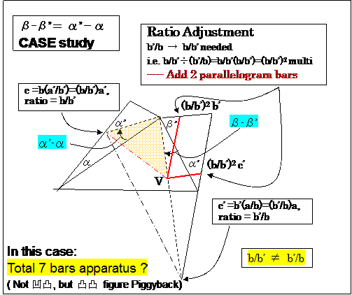 - Fig.1K -
Is this true? --- YES.
This is c = b(a'/b'), c' = b'(a/b) case:.
In this case, 2 Piggyback left & right bent triangles are both 凸.
But baby shape is not similar to the mother. (i.e. The head angle is the same, but base angles are not the same.)
We need the ratio adjustment to get the similar shape triangle.
Is there another more simpler way? --- Please investigate.
(Result: 「β-α'=β'-α」 method is superior to 「β-β'=α'-α」 method)
----------
As a matter of fact, (I found later),
(b/b')2c'=(b/b')2(b'/b)a=(b/b')a=ab/b'=a'b'/b'=a'
So, a', b' right hand 凸 bent bar is reduced to b', a' complement 凹 bent bar (= in Fig.1K more precise length red colored bent bar part).
Here, c'=(b/b')2b' (c' is V offset on b')
So, 7 bars can be reduced to 5 bars (i.e. original 凸 a', b' bent bar can omit. ).
[ c'/a'=(b/b')2b'/a'=b2/(a'b')=b2/(ab)=b/a --- i.e. c'=a'(b/a) --- new ratio at new situation.
And, left hand part is c=b(a'/b') (= not altered) ---- These values & shape are Fig.1J case itself. ]
- Fig.1K -
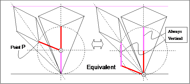
- Fig.2 -
We must recognize the above figure equivalency. ---- two selections (= the rabatment transformation).
Point P draws the same trace of circle.
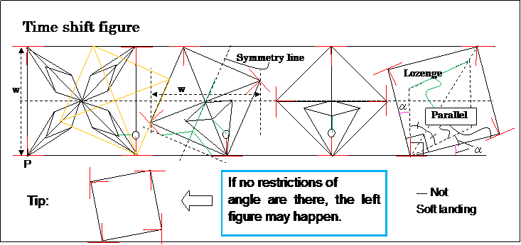
- Fig.3 -
( The trace of point P is linear. --- not cycloid.)
This apparatus makes Curve of constant width.
---- i.e. This apparatus also is a new loose "roller". (≒ rolling Jack (devise))
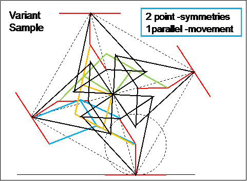
- Fig.4 -
Musashikoganei is the city name of my hometown in Tokyo JAPAN.
I have a copyright of this invention. I have ALL RIGHTS.
I recommend this material to be used for the high-school student lessons etc.
2. Generalization
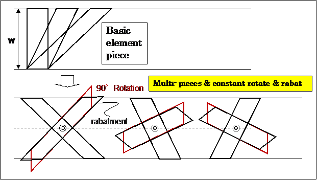
- Fig.5 -
rabatment = rabatment means the rotation of a plane into another plane about their line of intersection,
as in closing an open hinge. --- Geometric term ( bumped "rabat" sound ??).
Peaucellier Linkage or Chebyshev Linkage has above property.
(Chebyshev Linkage case makes hexagon (6 legs, 60 degrees angle). )
Below is a sample of element. (We can reduce the number of implement parts.)
----- 2nd element piece can be composed the lozenge linkage only.
---- Is this true? Please check out.
( Even if the Peaucellier Inversor is not touching the ground, it influences the shape.
The height and width are controlled by one Peaucellier Inversor restriction.
Two lozenges figure-A, figure-B are right angle relation, so shares the same diagonal lines. )
e
- Fig.6 -
But, center area is complicated.
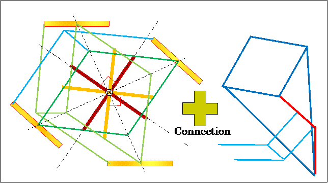
- Fig.7 -
Above left toy is interesting.
Pushing-pulling changes the square/ circle shape into small-big/ shrinking-expanding.
- In above figure, we can insert the Peaucellier Inversor into the lozenge half area (i.e. The center of lozenge is the top/ head of Inversor.).
--- Then, center area is not complicated.
3. Bipedalism ( or Bipedal Locomotion )
Perhaps, above square wheel model will give the good hint of Bipedalism (= two legs walking) model.
Please consider.
4. Others
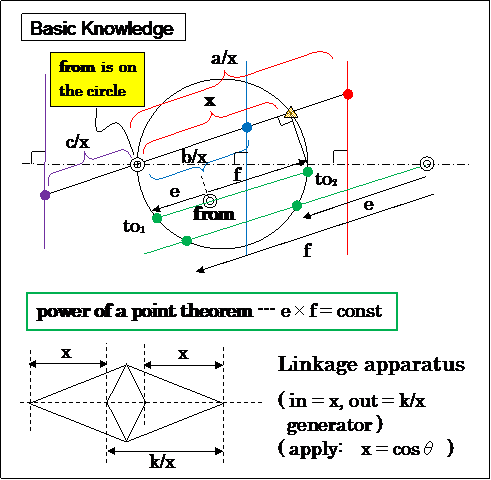
- Fig.8 -
cf. power of a point theorem --- figure is not comprehensive.
power of a point theorem --- Japanese site. picture is international.
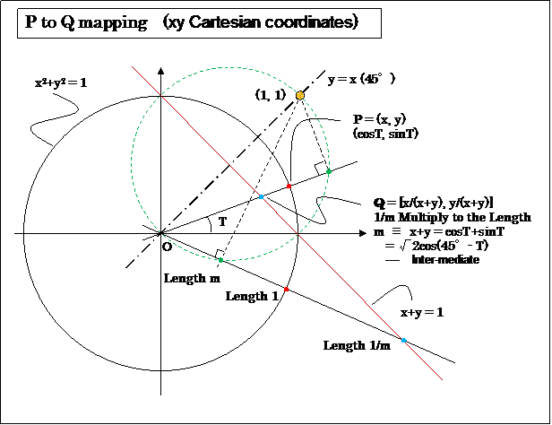
- Fig.9 -
Tip:
sin(A+B) = sinAcosB + cosAsinB (the sum identity in trigonometric)
sin(45°) = cos(45°) =1/√2, so, sin(45°+T) = sin(45°)cosT + cos(45°)sinT =1/√2(cosT + sinT)
∴ cosT + sinT = √2 sin(45°+T) = √2 cos(90° - 45°-T) = √2 cos(45°-T)
( x+y = 1, point Q parametric expression :
y= tanT x and x+y = 1 , then, x+ tanT x= (1+ tanT) x = (cosT +sinT)/cosT x = 1 , so, x = cosT/(cosT + sinT) )
Vector OP is circle [O is center, r = 1, x=cosT, y=sinT],
Vector (cosT+sinT) OP is circle [diameter √2], Vector 1/(cosT+sinT) OP is line.
x2 + y2 = 1, then ( x/(|x|+|y|), y/(|x|+|y|) ) mapping is the traces of the square shape.
( i.e. |x|+|y| = 1 or x= cos2T, y= sin2T )
Anyone/ Someone, please produce a drill of digging square using this property.
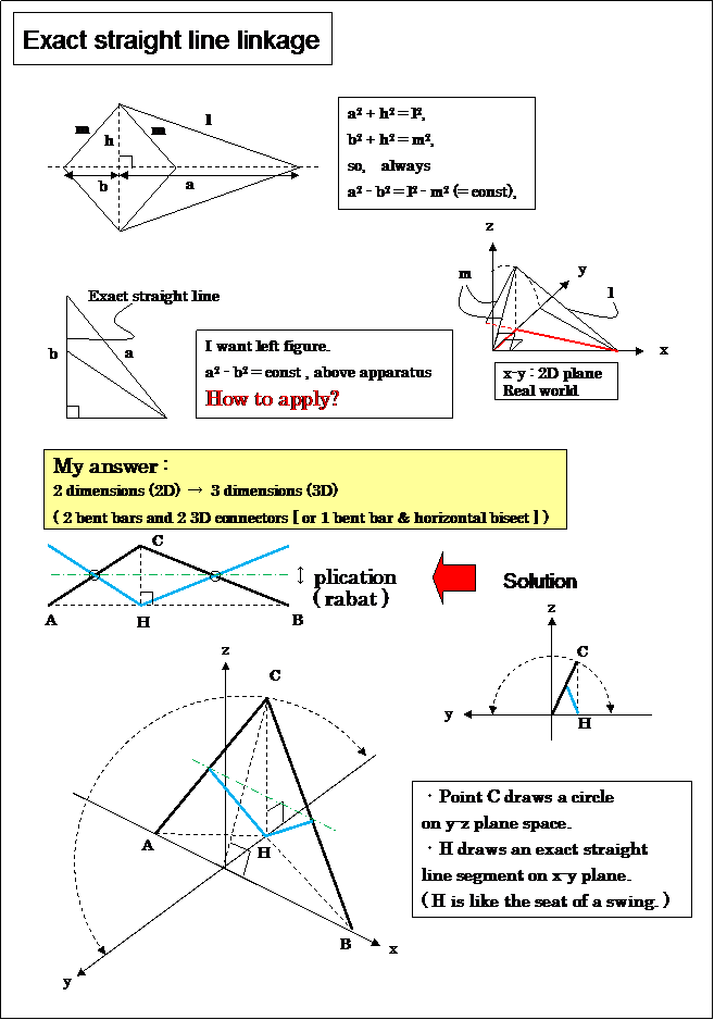
- Fig.10 -
Angle between a and b is 180° now, this must be more acute, so common h should be had z-axis direction,
and then I bend a straight line.
Looks like an Extended compass stationery?
(Sarrus's Linkage 3D hybrid ??)
cf. How to draw an exact straight line! (by © Dr Chris Sangwin)
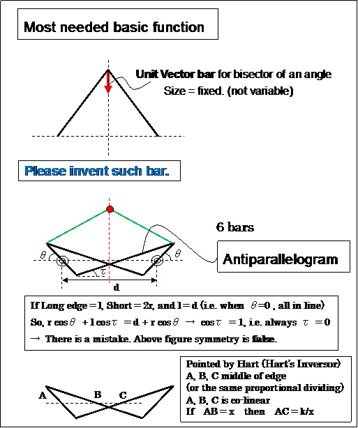
- Fig.11 -
I think that above function is the most needed.
If such function realized, the straight line can create very easily.
If 3D concept were applied/ allowed, it's easy.
i.e. Vector OP → a normalized vector OP / |OP|, such function.
( inversor is such converter device??? , maybe ???)
cf. Line-Symmetry trick. Fig. b. (written in Japanese) --- Is Fig.b. false? (Impossible layout?)
Q: What name is this linkage in English?
This property is like a gear.
--- This linkage is used in Hart's (exact straight line) Linkage.
Answer: Its name is "Antiparallelogram".
Antiparallelogram (en.wikipedia), Antiparallelogramme (fr.wikipedia)
Antiparallelograms are also called contraparallelograms or crossed parallelograms.
cf. Contraparallelogram (java.exe applet CPU 50%)
cf. Motion Geometry of Mechanisms - Page 206 - Google Books Result (Hart's Inversor)
Here is Anchor name "A-frame".
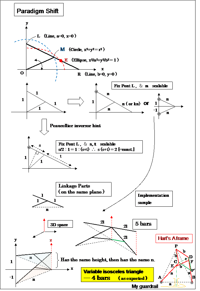
- Fig.12 -
- Fig.12 -
If we have a persistency "OL is variable", we fall in endless loop thinking.
We must create "input = circle, output = line" circumstance.
s, s+t =2/s ---- x (baby), 1/x (mother) line-segment comparison partition device. Find such device. ---- Easily found!!!
4 bars apparatus (same as Fig.10) is the minimum?
This is a Perpendicular bisector generator.
I think "This 3D 4-bars apparatus perhaps has 1 to 1 mapping relation to the 2D Hart's A-frame 5-bars apparatus.".
Is This true? Someone, Please reveal this my intuition.
Further, I think "This simple apparatus can be used for the Line-Symmetry mechanism with no-slide.". cf. Fig.18
(Someone, please prove this variable/ scalable isosceles (sound dict) device is the minimum device to draw exact straight line.
i.e. Smallest bar number of exact straight-line drawing linkage is 4. 3 is impossible, perhaps.)
This 3D 4 bars figure looks like a 2D Hart's linkage which has an antiparallelogram figure. (Force to 3D to 2D looking. There is one butterfly in it.)
cf. Hart's A frame ( ©Adaptable nonlinear bimode metamaterials using
rigid bars, pivots, and actuators. --- by Graeme Walter Milton)
--- 5 bars (This is a 2D version of above 3D 4 bars, perhaps.)
--- Figure 2: Figure (a) shows Hart's A frame. The black regions are rigid material. The
lengths are such that AC = BD = AB = a, PC = PD = EF = b, and CE = DF = c
and b2 = ac. For example, one may take a = 4, b = 2 and c = 1. The triangle APB
remains isosceles as the structure deforms.
(Hart's A frame 5 bars lengths depend on the base length of isosceles. but above 3D 4 bars are independent. ---- This is big !? )
cf. Video: Hart's A-frame (©How to draw an exact straight line!)
cf. Hart's A-frame figure drawing soft (©Chris Sangwin, 23 December 2006, Created with GeoGebra)
( |--- Sometimes (or Often), Ghost P' appears. --- I propose, to prevent this exchange, please prepare the short guardrail at middle area of AB. )
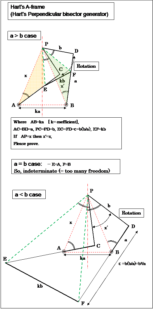
- Fig.13 -
My proof of Hart's A-frame. (This exercise is junior high school mathematical study level.)
I will prove "AP = BP (i.e. x = x')".
△ACP∽ △PCE (∵ b/a = c/b), same △BDP∽ △PDF, and further EF = kb = ka*(b/a)
so, △APB∽ △EPF (3 edges same proportion = b/a),
then ∠APE = ∠BPF (∵ non ∩ remaining part size are equal.)
and AP:PE (in both left edges) = BP:PF (in both right edges) = a:b (2 edges ratio & its including angle)
so △APE∽ △BPF ,
here (but, really) AE = a-c & BF = a-c --- i.e. AE = BF (This is strong. ※), so △APE ≡ △BPF (∵ similar ratio = 1)
then AP = BP
---- Further, △APB∽ △EPF∽ △CPD (has 3 similar isosceles generation), and △PCA ≡ △PDB
- Fig.13 -
(b > a case is the same, in a > b case figure, Change A, B to be free and then E, F fixed.)
(This apparatus key is "Similar scalable triangle whose base length is constant.".
Constant difference-length brings consistent angle-shift [= rotation]. This is special case. --- A kind of a fixed point algorithm or an invariant quantity law.)
My impression:
• Its shape looks like a " Weeping Woman 1937 " by Pablo Picasso . (© Succession Picasso/DACS 2002)
i.e. Cubism (3D to 2D mapping technique in art). Especially, her nose.
Be Crumple up , its feeling is also resemble.
• Like a Pregnant (including same DNA shape/ property in body). Matrix (= mother & babies).
• "a < b case" figure (lower part) structure has robustness. Please construct a this type swing in any park.
• "a = b case", Point E= Point A, Point F = Point B. i.e. the shrink occurs. And further if shrink didn't occur, the frame ACDB is parallelogram (i.e. AB // EF // CD), so the point P draws a pure circle (not a line).
(Analogy: In Peaucellier linkage, if outer bars were all the same length, become indeterminate.)
• This figure is very educational.
• I'm very angry that there is no web sites page which shows the mathematical proof (or evidence) of the Hart's A-frame linkage principle.
---- why? related Harry Hart.
• Suppose the case which the point P is most highest position. If PCA is straight (i.e. not bent), the EF length is (b+c)/(a+b) times than AB length. i.e. (b+c)/(a+b) = (b+b(b/a))/(a+b) = b/a. This value is matched to EF length definition.
This indicates that we can always have the maximum P position in which AC-CP are in line, and can exchange the left and right relationship beyond P.
• How did this idea/ law come to Mr. Harry Hart? Perhaps he got by try and error with real 4-bars linkage of perpendicular bisector test. (hypothesis and test cycle) --- It might be not as difficult as one would think. He should have written/ remained its discover history.
• Pair Peaucellier linkage reduced to Hart's A-frame? (7+7 → 5)
• Harry Hart (UK mathematician 1848-1920), You are the great as (or than) Harry Potter.
• They say that the name A-frame comes from A is "∧ (woodpecker's beak Mark or edge of isosceles triangle)" and a crossbar "-" is the EF bar in A-frame. That is "A" comes from its apparatus shape. i.e. "A-shaped" mechanism. derivation/ derive from. Oh! I understand. (So, a-frame is invalid.) cf. Image (Copyright © 2011 Algoryx Simulation AB.)
•
※: I'd like to point "Hart's A-frame apparatus is the special case of The
Circles of Apollonius apparatus".
i.e.
Harry Hart invented the general drawing apparatus of the Circles of Apollonius.
ex. In above Fig.13, we prepare the bar, such as, AC=a, CP=b and then BD=ua, DP=ub , where u = ratio of distance in the Circles of Apollonius. (i.e. Left hand
: Right hand =
1 : u size ratio enlargement for all things has be done. Left and right has similar figure elements.)
So,
In this situation, if EF=constant length (=kb) bar link. The point P draws
the circle. u ratio = 1 case, draws
the line (= linear).
(Set the point M on AB segment, where MB/AM = ratio u, If So, always ∠APM = ∠MPB [the same angle])
cf.
Circle of Apollonius (wikipedia, in Circle; with geometric proof),
Angle bisector theorem (wikipedia)
cf.
Orthodox proof for Angle bisector theorem (© The University of Georgia)
cf.
Locus of Points in a Given Ratio to Two Points (drawing soft; Copyright © 1996-2013 Alexander Bogomolny)
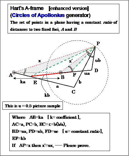
△APE∽ △BPF ,
here (but, really) AE = a-c & BF = u(a-c) --- i.e. BF/AE = u (This is strong. ※),
so △APE ∽ △BPF ( similar ratio = u)
then AP : BP = 1 : u (i.e. x' = ux)
- Fig.14 -
cf. §2.3 Hart's A-frame (©C. J. Sangwin , November 8, 2012,,,
~A fully detailed solution for Hart's A-frame is given below.~)
(Hence ABP is similar to RPS. misprint --- ABP is similar to RSP. or APB is similar to RPS.
Therefore �β2 + �α2 + η� = �α2 + η� + �β4. mislogic (I can't understand) --- β2 + η� = �α2 + η� + �β4 - α4. then β2 - α2 = β4 - α4
Triangles APC and BPC are congruent, misprint/ foolish APC ≡ BPD)
--- all broken !!!
I dare say to you, C. J. Sangwin --- Pardon me, but your logic is odd. defective. Do review.
Another proof by other person: (from by Google key-word "Hart's straight line mathematics" result.)
cf. Straight Line Mechanism due to Hart (1874)
---- My comment: you have not (common?) mathematical sense. ( This problem is easy. ) your proof is too difficult.
Your proof is so valuable as analytical numeric (algebraic) solution sample. (and, the book which you have is unkind. should be attached its geometric proof for readers.)
cf. Kempe's (Focal) Linkaget Generalized, particularly in
connection with Hart's second straight-line mechanism (© E. A. Dijksman)
cf. Hart's exact straight-line mechanism (Produced with EucliDraw©)
(~ Inspired from the book of Ivan Artobolevsky: Mechanisms in Modern Engineering Design bd I, p. 469, Mir Publishers, Moskow 1975. ~)
-- What is this? different type? ---- Please prove true. That introduced apparatus is A-frame family, but it's not A-frame. new apparatus. ---- This is great (see below Fig.). This is a A-frame concept root.
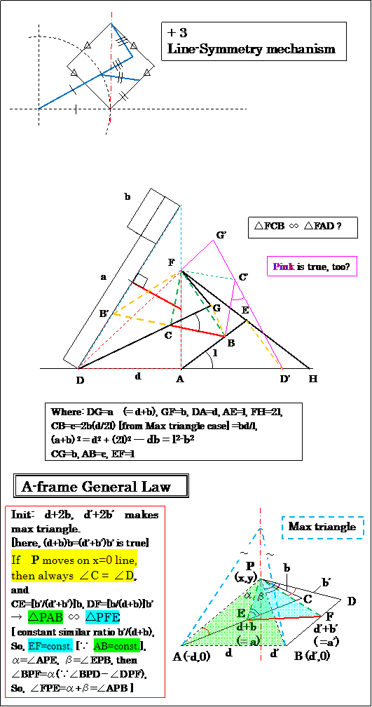
(Here, Anchor name = "Fig.15".)
- Fig.15 -
I've never had this good !
I think this apparatus is great useful.
Who invented this?
Harry Hart?
What's official name?
We should recognize this apparatus.
Please give me an elegant proof.
(--- Good pantagraph)
- My proof -
c=bd/l --- so, c/b = d/l (c:b = d:l)
--- this corresponds
BC:CG = DA:AE --- (1) --- inspired
Extend BC and Make B' (where B'C=BC)
So, perhaps
FB'CG ∽ FDAE
∵ ∠B'CG = ∠DAE (180° - ∠HAE)
and, from (1)
by "2 edges & including angle condition".
∴ △B'CG ∽ △DAE (similar ratio b:l)
Next,
db=l2-b2 , so, c=bd/l=l-b2/l -- so, BE=b2/l
then CG:BE=b:b2/l=l:b, DC:AB=d:bd/l=l:b -- so, DG:AK=l:b
, so, DG:FE=l:b
[another route: db=l2-b2, so b(d+b)=l2 so b/l=l/(d+b) ]
also, AE:CG=l:b (i.e. twice l:b mapping, (something recursive?))
[Summary: w=b/l, DG=a, AE=l=wa, b=w2a, d=(1-w2)a
, CB=AB=wd, BE=wb=w3a]
-- Next, check the Pythagorean (Law of cosines) --
Define T = ∠ FGD, S = ∠ FEA.
DF2=(d+b)2+b2-2(d+b)bcosT
AF2=2l2-2l2cosS=2l2(1-cosS)
DF2=AF2+d2 ---- (2)
(d+b)2+b2-2(d+b)bcosT=2l2(1-cosS)+d2
d2+2db+2b2-2dbcosT-2b2cosT=2l2(1-cosS)+d2
2db(1-cosT)+2b2(1-cosT)=2l2(1-cosS)
2(db+b2)(1-cosT)=2l2(1-cosS)
2l2(1-cosT)=2l2(1-cosS)
l2(cosS-cosT)=0 ---- ∴ S = T has given. --- i.e. If (2) is satisfied. then, Angle equivalence law exists.
later is easy. I will abbreviate.
∠FPE=∠APB is a great trick. --- Please see the figure in detail.
- Fig.15 -
Token memo: (Find my mistook point.) on 2013/04/20 --- no mistaken. This is another way proof.
I abandon (gave up) geometry. I do algebra. [reserve as a token of difficulty.]
A = (0,0), D=(-d,0), F=(x,y), db=l2-b2
C: (xC+d)2+yC2=d2, B: xB2+yB2= ((b/l)d)2, CB: (xB-xC)2+ (yB-yC)2=((b/l)d)2, G: (xG+d)2+yG2=(d+b)2, E: xE2+yE2= l2, GF: (x-xG)2+(y-yG)2=b2, EF: (x-xE)2+(y-yE)2=l2,
Please derive x=0
CB:-C:-B: -2xBxC-2dxC-d2-2yByC=((b/l)d)2-d2-((b/l)d)2=-d2 --- ① -2xBxC-2dxC-2yByC=0 i.e. xC(xB+d)+yCyB=0
This shows a fact, vector(xC-0,yC-0) ⊥ vector (xB+d,yB-0) i.e. AC ⊥ DB
GF:-G: x2-2xxG +y2-2yyG-2dxG-d2=b2-(d+b)2=-d(d+2b) --- ② x2-2xxG +y2-2yyG-2dxG+2bd=0
EF:-E: x2-2xxE+y2-2yyE=l2-l2=0 --- ③ x(x-2xE)+ y(y-2yE)=0 i.e. AF ⊥ (F to point 2AE)
②- ③: -2xxG -2yyG-2dxG+2bd +2xxE+2yyE=2x(xE-xG)+2y(yE-yG)-2dxG+2bd=0 --- ④ i.e.x(xE-xG)+y(yE-yG)-dxG+bd=0
I will show, ∠ FGD = ∠ FEA (by cos(∠ FGD) - cos(∠ FEA) = 0?, cos is available from inner product facility.)
Inner product DG*GF =(xG+d)(x-xG)+(yG-0)(y-yG)=(xG+d)x-xG2-dxG+yGy-yG2
AE*EF =(xE-0)(x-xE)+(yE-0)(y-yE)=xEx-xE2+yEy-yE2
from condition db=l2-b2 --- so, db+b2=l2 so, b(d+b)=l2
so DG*GF*(1/b(d+b))=AE*EF*(1/l2) check is equivalent to DG*GF=AE*EF check
DG*GF-AE*EF = (xG+d)x-xG2-dxG+yGy-yG2 - [xEx-xE2+yEy-yE2]=(xG-xE+d)x +(yG-yE)y-dxG-xG2-yG2+xE2+yE2=
adapt ④ (i.e. x(xE-xG)+y(yE-yG)=dxG-bd, so x(xG-xE)+y(yG-yE)=-dxG+bd)
= dx-dxG+bd-dxG-xG2-yG2+xE2+yE2
adapt xE2+yE2= l2, (xG+d)2+yG2=(d+b)2 --- xG2+2dxG+d2+yG2=d2+2db+b2 --- xG2+yG2=-2dxG+2db+b2
= dx-dxG+bd-dxG-(-2dxG+2db+b2)+l2=dx-db-b2+l2
=dx-db+(-b2+l2) = dx
---- Not zero. Is this true? ,,, I mistook??? ---pending calculation.
(item dx is isolated item, so, my calculation is perhaps true.)
if x=0 keeps by any method, so dx becomes zero.
This is what meaning ???, if the initial point is x=0 then it keeps 0. ????
(What is input? what is output? --- confusing.)
Please y=f(x) linear. and ff(x)=0 (y eliminated quadratic eq.) --- Solve this eq. x=0 is answer. try. I'm tired.
(x=0 , so dx=0, so two angles are always the same value.)
My Comment:
- When C becomes A is lawless area. become no-restriction. bar CB can move free. But Point F is remains on A (so, no problem?).
- Am I an archaeologist? Harry Hart should have inherited his writing material more.
- I can't prove yet. but I got Hart's thinking policy. That's next.
Prepare the 2 bent bars. One has a:b length ratio edges. Other has l:l ratio edges. Do exchange Cross/ Do hybrid. Divide a:b bars into l:l. Divide l:l bars into b:a (not a:b). And prepare one linking bar for the triangle base edge.
Anything good will happen. Maybe. --- Similar/ homothetic child triangle figure will be born. Angle value relation is conserved by shift movement.
- Is there any law? Angle 90゜ corresponds ratio 1:1? why? --- Please teach me.
I predicate "Angle 90゜ has no relation to ratio 1:1. other ratio can do. Please try." 1:1 is only (nothing more than) adopted as an easy sample.
---- No, 90゜ must correspond 1:1. This is A-frame key. Key is "bar is bent at (d+b) and b dividing point (not a and b)." So, 90゜ itself point (= the base point of perpendicular) is d=0, so bar was divided b:b (i.e. 1:1). On the contrary, d ≠ 0 case, can't be 1:1 (∵ d+b ≠ b). This is key Hart's A-frame algorithm key point. bar length initial condition is the Pythagorean theorem " (d+2b)2-d2=(d'+2b')2-d'2 --- 4b(d+b)=4b'(d'+b') --- i.e. ab=a'b'. i.e. a=d+b (depends on d) has special/ essential meaning. Other properties are also derivative from this.
In other words, 90゜ case is 1:1 , this indicates only depend a=d+b. so 90゜ has no special meaning.
What is this algorism in general? If there is a general theory, A-frame proof is more easy by using its theory.
i.e.
(1) Set maximum triangle . Each edge length are a+b, a'+b'. Set perpendicular line. Obtuse-angled triangle is OK, too.
(2) prepare 2 straight bars. each length are a+b, a'+b'.
(3) Bend the a+b bar at the point dividing a and b length.
(4) Using one shrunk small triangle, set the bent (a+b) bar on tne edge. Next, Bend the (a'+b') straight bar at arbitrary position, search the bending position which angel is equal to (a+b) bent bar's angle. a' and b' length are decided by this way. If failed to search, change the a:b ratio in (a+b) bar and retry. i.e. Go to back (3).
Tip: There exists ab=a'b' relationship, maybe. (why? I don't know.) → ( This is equal to the check the inner product [length of a projection × edge length]. area of rectangle. ab cosΘ & a'b' cosΘ )
(5) Now, bent (a+b) bar, (a'+b') bar are given/ gotten. these bent bars are always the same bending angle for any other shrunk triangle. This property is mysterious. why? I don't know.
(This is old. a=d+b, b=b solution is a tip of the iceberg. Many other pattern exists.)
■ How to get a:b proportion:
Above (2) to (5) search steps can be replace to next. (Very easy!!!)
• Give the name x=(a+b) bar, then, b=(x-d)/2, a= remainder of x.
• b'=(x'-d')/2, a'= remainder of x'
That's all. end.
(ab=a'b' is automatically satisfied.)
Tip: why d+b, b has special meaning? ex. d+b, 2b are wrong? why? Why isn't there other pattern?
---
Review result: (d+b, kb), (l,kl) bending proportion case, T and S relation is below.
2[l2-(1-k)b2]cosT -(1-k2)(l2-b2) =2kl2cosS (where, db=l2-b2)
So, k≠1 brings T≠S , k=1 causes T=S (only one case) i.e. k=1 is indispensable.
• Standard A-frame case, triangle is the isosceles triangle (i.e. |d|=|d'|). So, for Angle equivalence law, No needs d+b, b restriction.
|
(6) Find the c length position on the b which a:c = b':a' proportion.
As same, Find the c' length position on the b' which a':c' = b:a proportion.
In this way, We get new "A-frame" which makes the perpendicular line at any proportion point between (or out of) 2 fixed points.
- 2 angles equality is conserved.
- Similar/ homothetic child triangle has constant similar ratio to the parent. So, base length of triangle is constant in any time (for any deformation).
This is general/ generalization theory. very simple.
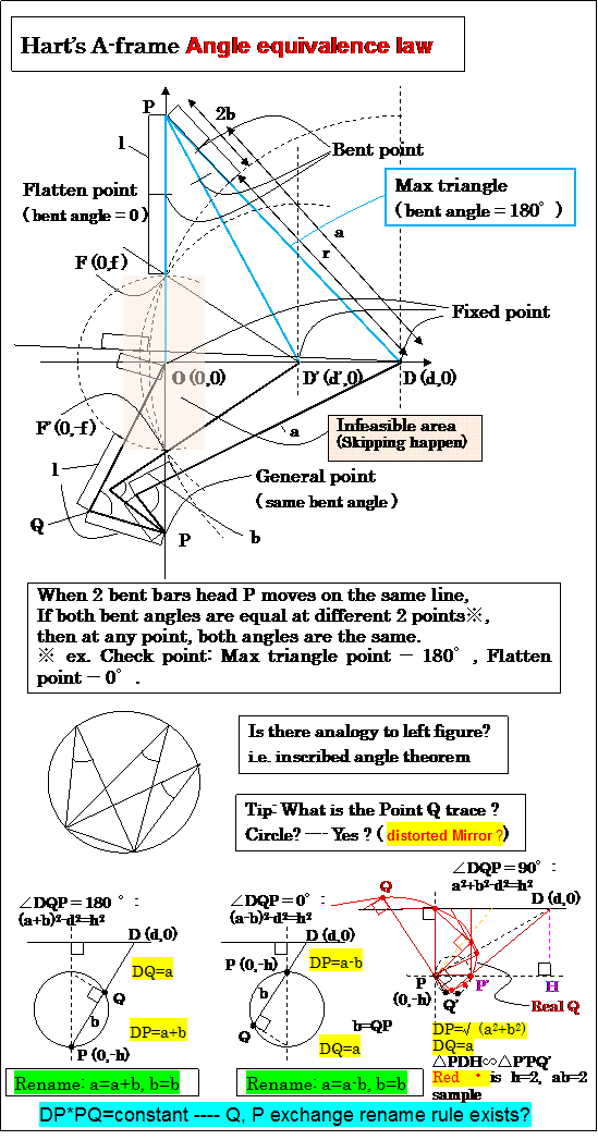
bar length condition [at flatten point]
d=d case:
r2=d2+f2 -- r=sqrt(d2+f2)
b = any
i.e. a=r+b, b=b length=r+2b
d=0 case: ---a=f+l, b=l length=f+2l
initial condition [at max triangle]
(r+2b)2=(f+2l)2+d2
r2+4br+4b2=f2+4fl+4l2+d2
d2+f2+4br+4b2=f2+4fl+4l2+d2
4br+4b2= 4fl+4l2 ---br+b2=fl+l2 i.e. b(r+b)=l(l+f)
In general condition:
DP2=(r+b)2+b2-2(r+b)bcosT
OP2=(l+f)2+l2-2(l+f)lcosS
DP2=OP2+d2 --- (1)
We estimate (1);
(r+b)2+b2-2(r+b)bcosT = (l+f)2+l2-2(l+f)lcosS +d2
r2+2br+b2+b2-2brcosT-2b2cosT=l2+2fl+f2+l2-2(l+f)lcosS +d2
d2+f2+2br+2b2-2brcosT-2b2cosT=2l2+2fl+f2-2(l+f)lcosS +d2
2br(1-cosT)+2b2(1-cosT)=2(l+f)l-2(l+f)lcosS
2(br+b2)(1-cosT)=2(l+f)l(1-cosS)
2(fl+l2)(1-cosT)=2(l+f)l(1-cosS)
2(l+f)l(1-cosT)=2(l+f)l(1-cosS)
2(l+f)l(cosS-cosT)=0
So, (1) is eq. to cosT=cosS --- T=S
i.e. bent angles are the same for the different fixed point bent bars.
(f=0 case proof result is in Fig.15)
f=0 is preferable? --- Because, There is No infeasible area.
Duality of Hart's A-frame vs. Peaucellier linkage is on the distorted mirror world (= warp). It looks so.
Notation of the point Q and P must be exchanged. Something odd. warped.
----- Please investigate this distortion reason.
In mirror world, the trace of point Q is a circle curve. In real world, It's not circle , it's perhaps quartic function (degree 4) (?). ---- bent angle= 0 or 180° case are only circle, other angles case are not circle, perhaps.
The magic of inversor was hidden in "Law of cosines". This property can be derived from Hart's A-frame concept.
Rename modification makes the system consistency. (?) ---- Please consider.
[ PP' // D horizontal line, PD*PQ'=PP'*DH=(2r)h=const (i.e. constant △ area). PQ' length =distance from P' to PD: This is variation of inverse property? ]
- Fig.16 -
Above Fig. is interesting.
Change the point of view, See the lower part of figure, if P (vertical moving) is fixed , and O, D', D points series are on the same line (horizontal moving), that is from P, the arm length changing apparatus PD, PD', PO, such apparatus is a new exact line drawing apparatus.---- this apparatus is alike a Peaucellier linkage (inversor method tool).
D, D',O are connected the rule ab product value is constant.
That is " product(= multiplication) value is constant" ---- This indicates that
"In A-frame, the bars group member has the property "ab=constant" ---- this is the inverse property itself. So, Peaucellier inversor and Hart's A-frame both concept are connected in the under-world.
A kind of duality, perhaps."
vertical moving vs. horizontal moving (perpendicular vs. horizontal-line, orthogonal relation), same bent angle vs. same product value (d changing & angle const. vs. d const. & angle changing).
(Peaucellier linkage is bent angle is set/ implemented 0° or 180° constant.)
--- equal-area problem --- rectangle (90° constant [wide☓height])--- triangle are ---- parallel head moving (= line)
<Memo>
In general S=T is needed below.
a2+b2-2abcosT-d2=a'2+b'2-2a'b'cosS-d'2
ab=a'b' ---- [0] --- (strong condition)
a2+b2-d2-(a'2+b'2-d'2)=2ab(cosT-cosS)
So, Any a, b, d, a', b', d' which satisfy
a2+b2-d2-(a'2+b'2-d'2)=0, and ab=a'b' ---[1] --- (This is just very the general equation which I wanted.)
are always inducing/ reducing T=S
---- i.e. The number of bar length satisfying solutions are infinite ∞.
(i.e. Answer is not one. Many answers are there.)
(a=d+b, b=b is a versatile solution, but it's a tip of the iceberg. )
Ex1.
So, If a2+b2-d2=kab (k= parametric parameter/ coefficient)
a=d+b,b=b, case is k=2. (∵ if a=d+b : (d+b)2+b2-d2=2db+2b2=2(d+b)b=2ab [this is identical equation] --- i.e. k=2)
a=d+b, b=b is one very valuable smart general solution.
(kab=2ab=2abcos0° --- k=2 corresponding to angle = 0°.)
i.e. having angle=0 at same point (ex. at point O), is comes from a2+b2-2abcos0=d2, i.e. (a-b)2=d2 --- a-b=± d ---a-b=d then a=d+b (naturally reduced) [a=b-d -- interesting, bent at back over/ beyond point D. long b, this is nice(?) --- complementary]
Ex2.
k=0 case sample (a2+b2-d2=0);
a=3, b=4, d=5, ab=12, angle=90°, one sample pair a'=b'=√12, d'=√24, a'b'=12, angle=90°
--- what happens by this? d'=√24 is almost 5 (=√25). Does it work correctly?
(a'=6, b'=2, d'=√40=6.32.., a'b'=12 is more good pair? ,,, maybe )
Ex3.
a=b=d=4, ab=16, angle = 60°, try
cos60=1/2
suppose a=8, b=2, so
a2+b2-2abcos60=d2
64+4-32/2=68-16=52 --so, d=√52=7.211... Good taste.
2nd Theorem
(1) ab=a'b'
(2) Under satisfying (1) rule,
At any one point※ on the line which is not the Max triangle point, If both angles are the same, then at other any point, both angles are the same.
※: I recommend the point O.
|
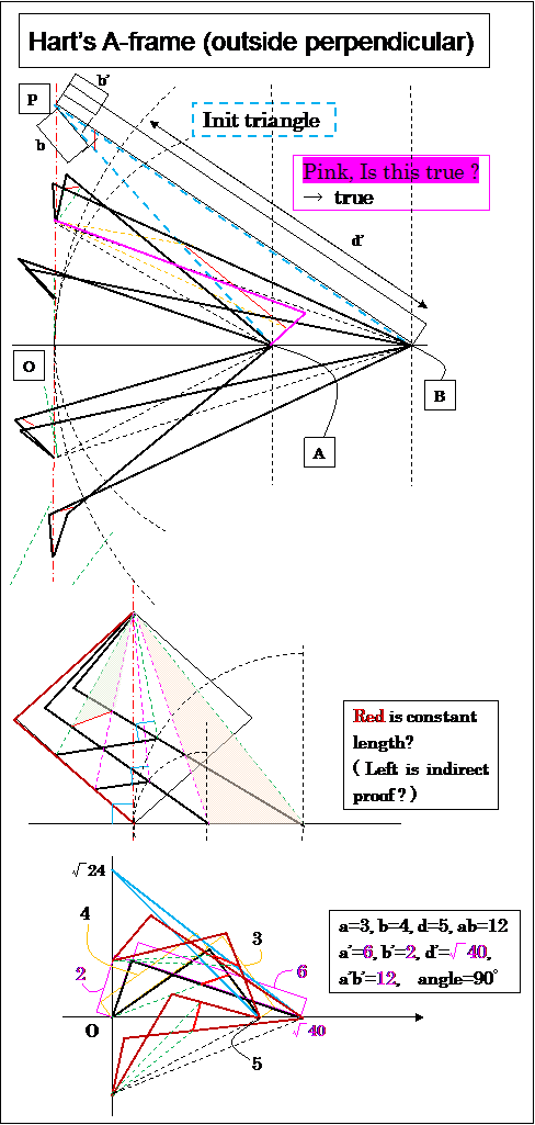
Pink line is suggestive.
This indicates
"bent proportion is d+b:b, reverse b:d+b (or b:b+d) is OK, too".
---- A kind of complementary.
In init triangle, next is true.
b+c=b+b(b'/a')=b(1+b'/a')=b(a'+b')/a',
also,
b'+c'=b'(a+b)/a ---(1)
--- then (b+c)/(b'+c')=[b(a'+b')/a']*[a/b'(a+b)]=[ab/(a'b')][(a'+b')/(a+b)]=(a'+b')/(a+b)=BP/AP
i.e. homothetic child triangle is similar to parent.
but (b'+c') corresponds to (a+b), (b+c) is to (a'+b') [Cross happens].
Similar ratio is (b'+c')/(a+b)=b'/a (from (1))
So, we prepare the bridge bar (red bar in left Fig.) which length base AB multiply b'/a.
Left figure teach us.
a=d+b, b=b (a2+b2-d2=2ab) is, a&b angle=0 at Point O [Angle range =0 to 180 degree].
but
a2+b2-d2=0
is , a&b angle=90° at Point O [Angle range =90 to 180 degree].
--- so, It doesn't happen the flatten phenomena.
stable, robustness apparatus than usual A-frame.
[ex. It doesn't go to the ghost route (= mistaken route). ]
--- This is good property.
Someone,
Please submit the demonstration video of left sample to YouTube.
(YouTube's present "A-frame" VTR is somewhat unsmooth motion. It's not good. Left (3,4,5) sample motion is as smooth as Peaucellier Linkage apparatus, perhaps.)
--- Looks like a wingstroke. beautiful a bit (?)
Parameter:
a=3, b=4, d=5
a'=6, b'=2, d'=√40 (=6.324555..)
c=b(b'/a')=4(2/6)=8/6=4/3=1.3333
c'=b'(b/a)=2(4/3)=8/3=2.6666
bridge bar=|d-d'|(b'/a)=(6.324555-5)(2/3)=0.883037
( I tested with GeoGebra drawing tool. --- The result was very good. No ghost route appeared. stable.)
Generalized Hart's A-frame Online DEMO (© F.IMAI, GeoGebra Java applet)
cf. DownLoad demo GeoGebra original file, if you want (Especially, if you want to verify another parameter test, please use this.). G_A-frame.ggb (file-size= 11KB, (3/4/5,6/2 pair) made by F.IMAI on 2013/05/03) ---- If download file name were G_A-frame.zip, After download, Modify the file name from "G_A-frame.zip" to "G_A-frame.ggb" by hand (change the file extension.).
( I tried making HTML from GeoGebra export function [= Dynamic Worksheet as Webpage (html) ], but error always happened. So, I gave up. GeoGebra bug??? [He says "it looks like you don't have Java installed, please go to www.java.com.", ---- Stop joking !!!]
-- This is bug. I found the answer from Google "java.lang.ClassNotFoundException: geogebra.GeoGebraApplet Unknown Source". Answer is load: class geogebra.GeoGebraApplet not found. Problem (Jan 31, 2012 --- the same my case.), Debugging: Applet fails to load, --- So, I modified the html source as "-Djnlp.packEnabled=true" to "-Djnlp.packEnabled=truexxx" in <param> tag. --- so, bug was fixed, and applet worked. very good!!!
Tip: I changed the applet language from Japanese to English for international use. cf. Reference:Applet Parameters )
- Fig.17 -
At now point, above figure is somewhat lack of accuracy/ odd. but feeling is true. So, sufficient.
Where is odd? --- ex. P just on O, triangle is not flattened, this is odd. Because if a=d+b, b were composed, d point is just on the O, b and b must be overlapped completely (at outside from O). Now status: ---- by After my review, my original figure (unfortunately, already omited) was true. My heuristic observation was true. Flatten point can change. i.e. not (0,0) , to (0,f) [f= flatten point height offset].
We should recognize the result of above Fig..
Perhaps, my above indirect proof feeling is true. Brown bar is an intermediate medium. --- i.e. We can get a,b, a', b' length/ size by "Right triangle Hart's A-frame" algorithm.
(i.e. d, d' are distance from the perpendicular base. b, b' are arbitrary. a=d+b, a'=d'+b', ab=a'b'=l2 (i.e. b/l=l/a, b'/l=l/a'), The ratio from parent to Similar/ homothetic child triangle =b'/(d+b)=b'/a or b/(d'+b')=b/a' or bb'/l2=bb'/ab=bb'/a'b'. )
Simpler than Peaucellier linkage apparatus (This layout is near/ alike the typical Peaucellier model.).
(When Fig.17 applies to Fig.1, ...... ------ one sample is added as Fig.1H on 2013/04/25)
Below ↓ material is related to above ↑.(?) --- but, too difficult. (I deeply checked, I found, this material not difficult. but, Not related to generalized (d+b, b) story.)
cf. Kempe's (Focal) Linkage Generalized, particularly in
connection with Hart's second straight-line mechanism (.PDF)
by © E. A. Dijksman (Received on 19 April 1974)
Below ※ ↓ is related to generalized A-frame, pretty much. Figure 7 (A random 4-bar and a reflected similar one, built on top) , a/b/c/d lengths are general/ random values, distance
e are generalized parameter. Figure 7 itself is a Generalized A-frame indeed. But, he (she?) was unaware (or, didn't emphasize [ ∵ of course property!!!]) of the inverse law concept (corresponding to ab=a'b'=constant in my material, In this book, ac'=a'c exists ∵ a'/a=b'/b=c'/c=d'/d=
b/d=similar ratio. but no importance appeal.). Figure 8 (Hart's 2
nd straight-line mechanism incorporated) is, too.
Figure 7, 8 description & proof is very interesting & useful/ educational. Like a Parallel cushion (or spring) mechanism. ◢ + ◤ ≒ ◩,
≒ reverse dip-slip fault, Who found Figure 7?, he/ she had good sense.
But, The generalization of A-frame written in this book was not prevailing at all (= No one knew about). Who should be blamed? ----- Summing up,
No enlightenment activities have done. [lack of sensibility of true importance] ,,, [Figure 13. where has gone? missing]
※ cf.
"True straight-line linkages having a rectilinear translating bar" (.PDF) by © E. A. Dijksman (This is linked from wikipedia
"Hart's inversor" --- This is linked from wikipedia
"Straight line mechanism" as "Hart's A-frame".) ---- in Advances in Robot Kinematics and Computational Geometry, 4 ARK, Ljubljana, July 6, 1994. Kluwer Academic Publishers (1994), p.411-420.
My question: In Figure 7, Even if the point A
0, B
0, B, A were fixed, B' or A' can move freely, segment B'A' is not ensured horizontal.
( If you have a leisure, try Figure 7 with GeoGebra toy. --- very tired. )
This is a good geometry exercise/ problem for adult. Please challenge.
---- This is difficult(?).
---- This apparatus is superior to original Hart's A-frame. ---- I think so.
cf. setting variation [Guida rettilinea di Hart (2°) ]. (= not general)
|--- [ easy setting result: b=d, l=√2 d, case]
cf. Another sample by EucliDraw© ----- This is only a complementary case.
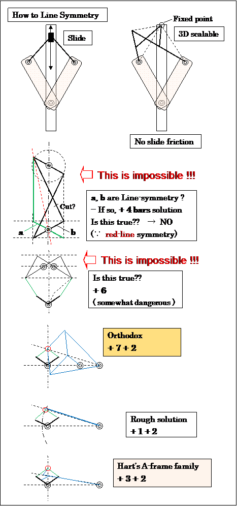
- Fig.18 -
• You may exchange the slider part into the exact straight line apparatus.
→ In general, this is the best and stable (no-dangerous). --- Most Orthodox
→ If precision is not needed, rough technique is sufficient.
ex. Except 0 degree, 180 degree --- unmatch is allowed. ,,, etc.
• How should we make the hinge?
• Can't go across beyond the symmetry line. --- Please consider how to delete this restriction.
Exercise-1 : Apply Line-symmetry technique to Fig.1
Exercise-2 : Apply Hart's A-frame to Fig.1
Exercise-3 : Apply Hart's A-frame to Ellipse curve drawing (5 + 2 bars: see Fig.12 ---- red curve)
(My Q: in Fig.13, C is circle, P is line. So, The point between P and C is Ellipse?)
One sample of Hart's A-frame for the wheel.
cf. Roly-poly toy (wikipedia).
In Japanese, Silk ball/ silkworm egg (cocoon) rolling.
ex. The caster wheel on the beach.
cf. Images for wheel on the beach - Report images (by ©Google "wheel on the beach" keyword result)
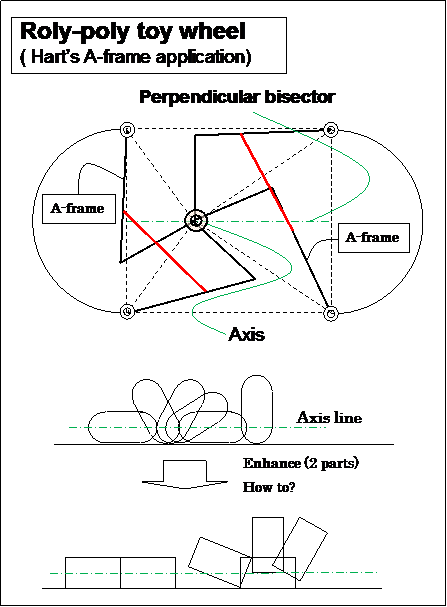
- Fig.19 -
The Rolling Swing wheel. --- walking legs.
(2 pendulum apparatus. The swing whose leg length is variable.)
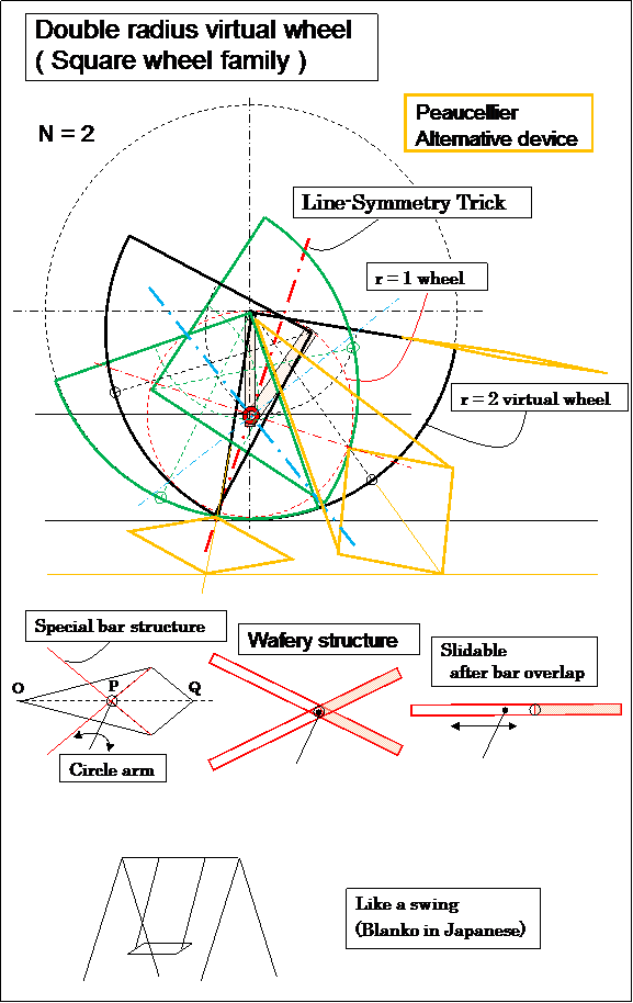
- Fig.20 -
r = 1 circle ⇔ r = 2, 90° sector × 2, Line-symmetry mechanics × 1
(Gravity hanging is needed to keep the vertical line.
The axis of this wheel is like a seat of a swing.)
Same analogy can be applied to the Peaucellier device.
Peaucellier inversor devices can use to replace this. ---- i.e. 2nd Peaucellier inversor application.
(different usage of inversor from 1st application. Top and foot are replaced/ reversed.)
(Extended Peaucellier Inversor: OP × OQ = const. But real world OQ has upper limit even as OP could have 0.
---- So, After the lozenge became flat-topped, it needs slidable OP length trick.
Above figure shows such a trick solution sample.)
Simple sample of above.
One of the Bipedal Locomotion mechanism.
(If necessary, please make 2 sets in order to touch on the earth at 2 points always.)
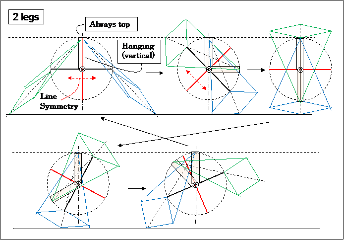
- Fig.21 -
Backwards speed is twice.
If 2 sets are made, the number of leg is 4.
--- This is simple, but is not clever, it should be one set of 3 legs
(i.e. 2 legs are always on the earth [ and top angle is 45°], and another 1 is in backward moving.)
--- Please consider such apparatus.
Example.
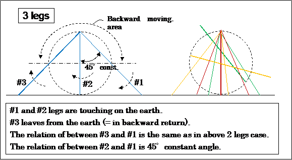
- Fig.22 -
More simpler.
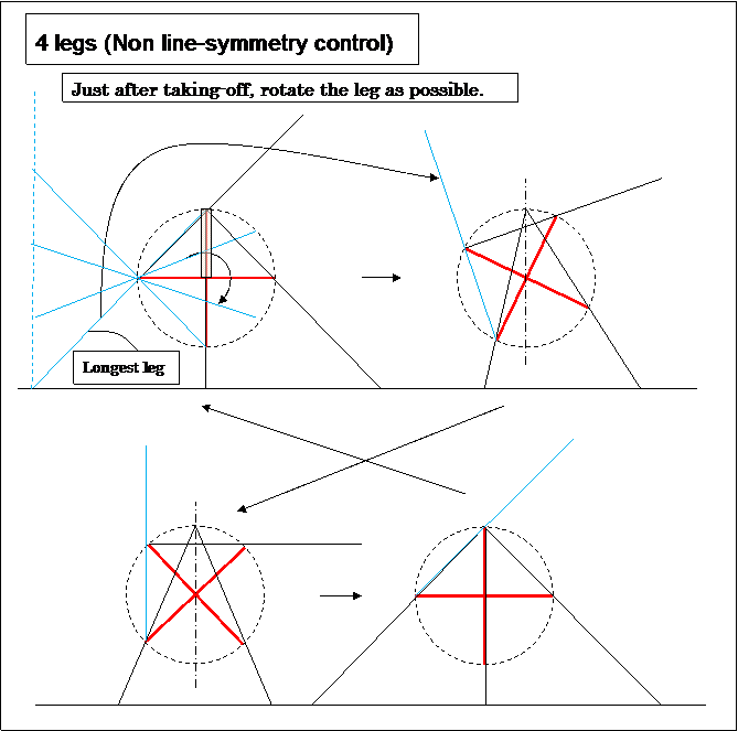
- Fig.23 -
If duality theorem were there in this wheel, Fig.1 and Fig.23 would be linked by the duality, I think so.
In Fig.1 the line-symmetry was reduced to the parallel-mechanism, but, why can't apply its trick in Fig.21.
Please consider.
Links:
• The back of isosceles triangle (written in Japanese)
• Images for Square Wheels (by Google "Square Wheels" keyword serch result)
• BASICS OF MECHANISMS (.pdf)
• Continuous track --- somewhat non-intelligent?
(ex.: Bicycle with Peaucellier Linkage Wheel. ---- Run on ice skate link.)
• Pedrail wheel
|---- cyberneticzoo.com (a history of cybernetic animals and early robots
)
• Surprises in Mathematics Part 1 of 2 , 2/2 --- VTR by Dr. Stan Wagon Professor of Mathematics - Macalester College.
(Square-Wheeled Tricycle, Reuleaux triangle etc.)
Link free. (C) 2013, F.IMAI , All Rights Reserved.


 by Point H. --- very easy.)


 - Fig.1J -
 - Fig.1K -


